


33 Applied Instructions (Extension File Register Control)
33.4 LOGR / Logging R and ER
762
FXCPU Structured Programming Manual
[Basic & Applied Instruction]
Function and operation explanation
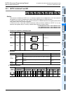
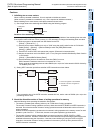
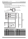
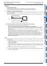
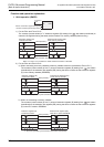
1. 16-bit operation (LOGR/LOGRP)
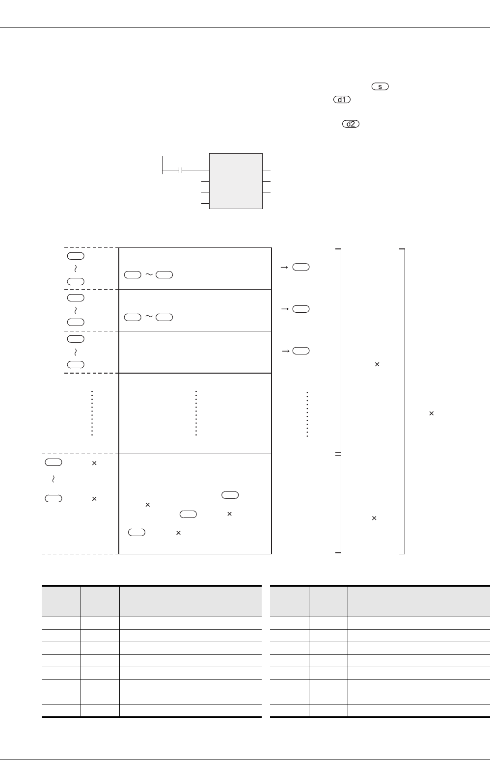
While the instruction is driven, "m" devices starting from the device specified by are logged until "n"
sectors of extension registers (R) starting from the device specified by and extension file registers (ER)
in a memory cassette are filled.
The number of pieces of logged data is stored to the device specified by .
If a memory cassette is not used, data is not written to extension file registers (ER).
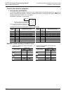
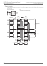
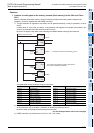
Logging data format
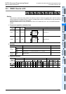
The table below shows the head device number in each sector.
Sector
number
Head
device
number
Written device range
Sector
number
Head
device
number
Written device range
Sector 0 R0 R0 to R2047, ER0 to ER2047 Sector 8 R16384 R16384 to R18431, ER16384 to ER18431
Sector 1 R2048 R2048 to R4095, ER2048 to ER4095 Sector 9 R18432 R18432 to R20479, ER18432 to ER20479
Sector 2 R4096 R4096 to R6143, ER4096 to ER6143 Sector 10 R20480 R20480 to R22527, ER20480 to ER22527
Sector 3 R6144 R6144 to R8191, ER6144 to ER8191 Sector 11 R22528 R22528 to R24575, ER22528 to ER24575
Sector 4 R8192 R8192 to R10239, ER8192 to ER10239 Sector 12 R24576 R24576 to R26623, ER24576 to ER26623
Sector 5 R10240 R10240 to R12287, ER10240 to ER12287 Sector 13 R26624 R26624 to R28671, ER26624 to ER28671
Sector 6 R12288 R12288 to R14335, ER12288 to ER14335 Sector 14 R28672 R28672 to R30719, ER28672 to ER30719
Sector 7 R14336 R14336 to R16383, ER14336 to ER16383 Sector 15 R30720 R30720 to R32767, ER30720 to ER32767
LOGRP
EN ENO
s
m
n
d1
d2
Command
input
Head device to be logged
Number of devices to be logged
Number of sectors of devices used in logging
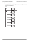
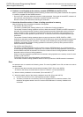
Head device used in logging
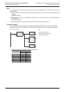
Number of pieces of logged data
Destination storing 1st logging data
+m-1
Destination storing 2nd logging data
+m-1
Destination storing 3rd logging data
+m-1
+2m-1
+m
+3m-1
+2m
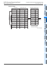
+(1926 n)-1
+(2048 n)-1
Number of
stored data
= m
= 2m
= 3m
Data writing
area
1926 n
Data writing
position control
area
122 n
Logging data
storage area
2048 n
s
d1
d1
d1
d1
d1
d1
s
s s
d1
d1
d1
d1
d1
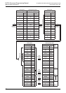
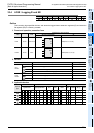
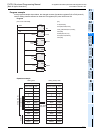
Writing position control area
(Every time one word is used in the data
writing area, bits are set to OFF (0) from
ON (1) in turn from bit 0 of [ +
(1926 n) - 1].
After bit 15 of [ + (1926 n) - 1] is
set to OFF (0), bit 0 of the next device
[ + (1926 n)] is set to OFF (0) in
the next logging.)
d1
d1
d1