


5 Basic Instruction
5.10 SET, RST
83
FXCPU Structured Programming Manual
[Basic & Applied Instruction]
1
Outline
2
Instruction List
3
Configuration of
Instruction
4
How to Read
Explanation of
Instructions
5
Basic Instruction
6
Step Ladder
Instructions
7
Applied Instructions
(Program Flow)
8
Applied Instructions
(Move and
Compare)
9
Applied Instructions
(Arithmetic and
Logical Operation)
10
Applied Instructions
(Rotation and
Shift Operation)
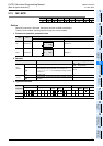
2. When using word device (timer or counter)
Use RST instruction to reset a counter or retentive type timer.
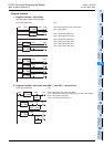
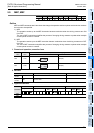
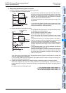
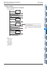
1) Program example of an internal counter
C0 up-counts the number of turning ON from OFF at X011.
When the counting result reaches the set value K10, the output
contact C0 is activated. Even if X011 changes from OFF to ON
after that, the current value of the counter remains unchanged
and the output contact remains activated.
For clearing the counter and returning the output contact, X010
is set to ON.
In case of latched (battery backed) type counters, the current
value and the operation status and reset status of the output
contact are latched even after power failure.
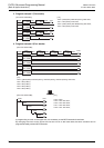
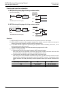
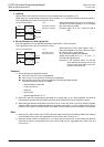
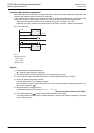
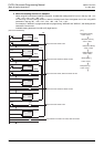
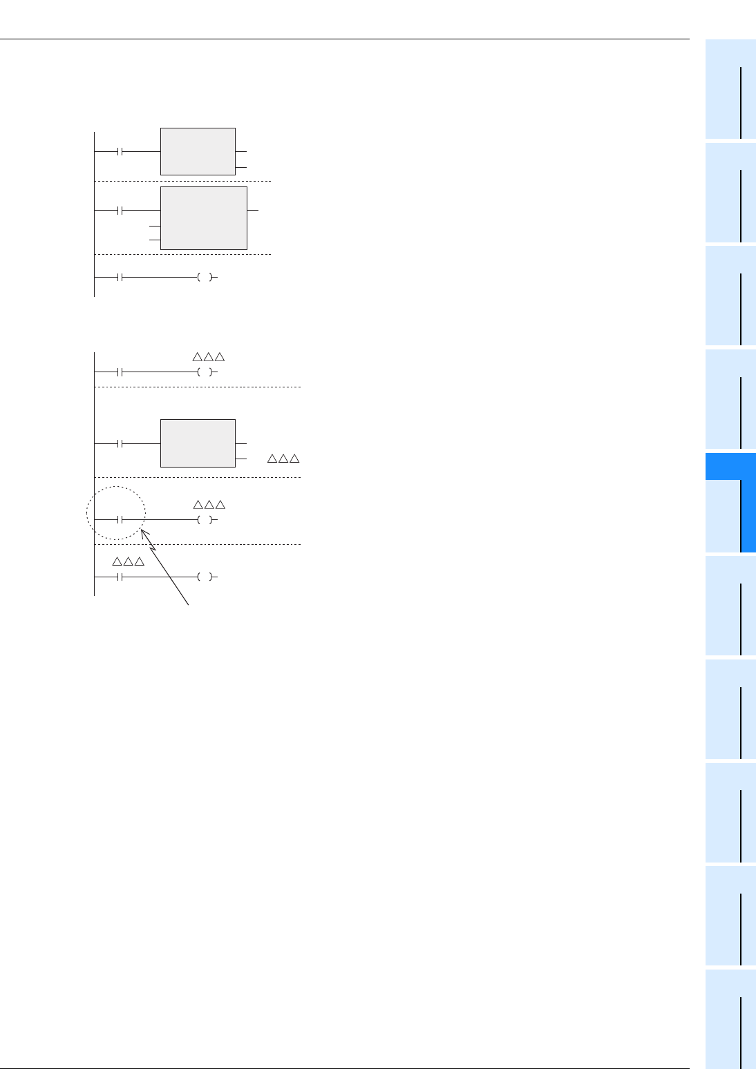
2) Program example of a high speed counter
For one-phase one-input counters, use special auxiliary relays
for specifying the counting direction.
X010 in ON status: specifies down counting.
X010 in OFF status: Specifies up counting
When X011 turns ON, the output contact of the counter
CUUU is returned and the current value of the counter is reset
to "0".
In counters with reset input, the same situation is achieved by
interrupt operation when the corresponding reset input turns
ON, but any program is not required for this operation.
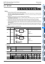
When X012 turns ON, turning ON/OFF of a counting input X000
to X005 determined according to the counter number is
counted.
In counters having start input, counting is started only after the
corresponding start input turns ON.
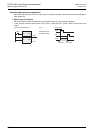
When the current value of a counter increases and reaches the
set value (K or contents of D), the output contact is set. When
the current value decreases and reaches the set value, the
output contact is reset.
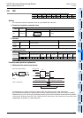
As a contact driving the counting coil of a high speed counter, program a contact which is normally ON
when high speed counting is executed.
If an input relay (X000 to X005) assigned for high speed counters is used for driving the counting coil,
accurate counting cannot be achieved.
3) Caution on using RST instruction for a jumped program, subroutine program or interrupt program
When RST instruction for a timer or counter is executed in a jumped program, subroutine program or
interrupt program, the timer or counter may be kept in the reset status and the timer or counter may be
disabled.
For details, refer to the following sections.
→ For a jumped program, refer to section 7.1.
→ For a subroutine program, refer to section 7.2.
→ For an interrupt program, refer to section 7.3.
CS0
RST
EN ENO
d
CN0
X010
OUT_C
EN ENO
CC0
X011
CCoil
CValue
K10
Y003
Counting direction
Sequence
reset circuit
K or D
Counting coil
X010 M8
RST
EN ENO
d
CN
X011
X012 CC
CS Y002