


12 Applied Instructions (High Speed Processing)
264
FXCPU Structured Programming Manual
[Basic & Applied Instruction]
12.3 MTR / Input Matrix
Function and operation explanation
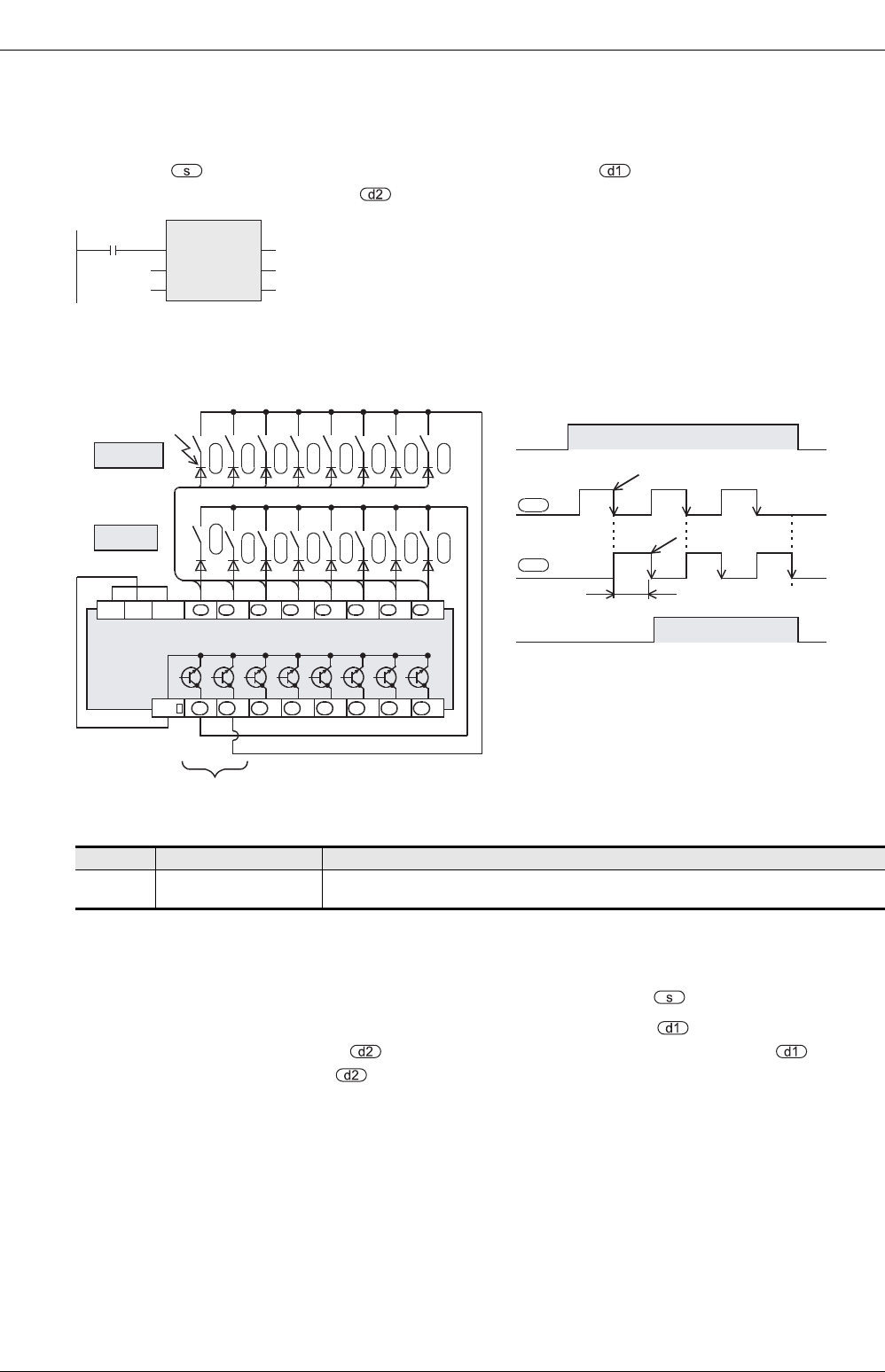
1. 16-bit operation (MTR)
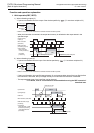
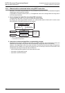
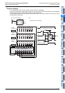
An input signal of 8 points × "n" columns is controlled in the time division method using 8 inputs of the device
specified by and "n" transistor outputs of the device specified by . Each column is read in turn, and
then output to the device specified by .
For each output, the I/O processing is executed immediately in turn in interrupt at every 20 ms under
consideration of the input filter response delay of 10 ms.
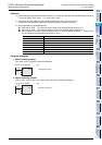
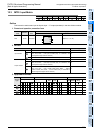
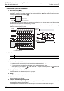
The figure below shows an example of the FX
3U series main unit (sink input / sink output). For the wiring,
refer to the manual of the PLC used.
Related devices
Cautions
1. Number of occupied devices
1) Eight input points are occupied from the input device number specified in .
2) "n" output points are occupied from the output device number specified in .
When specifying the output in , make sure that "n" output numbers specified in does not
overlap the output specified in .
2. Limitation in the number of instructions
The MTR instruction can be used only once in a program.
3. Wiring
One diode of 0.1A/50V is required for each switch.
4. Output format
Use the transistor output format.
5. Cautions about writing during RUN
Even if an operand device is changed by write during RUN while the MTR instruction is executed, the PLC
operates using the device before change.
The changed device is reflected after the command input is set to OFF once and set to ON again.
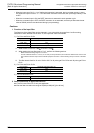
Device Name Description
M8029
Instruction execution
complete
Turns ON after the first cycle operation
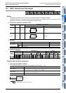
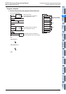
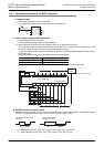
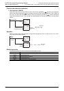
MTR
EN
s
n
ENO
d1
d2
Input number
Output number
ON output destination
Number of
columns
Command input
(normally ON)
M8029
(Execution complete)
1)
4)
+1
2)
20ms
3)
6)
5)
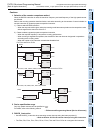
COM +1 +2 +3 +4 +5 +6 +7
S/S
+1 +2 +3 +4 +5 +6 +7
+1
+2
+3
+4
+5
+6
+7
+10
+11
+12
+13
+14
+15
+16
+17
0V24V
s s s s sss s
d1d1 d1 d1 d1 d1 d1 d1
d1
d1
d2
d2
d2
d2
d2
d2
d2
d2
d2
d2
d2
d2
d2
d2
d2
d2
Diode
0.1A(50V)
Command
contact
1st column input is received.
2nd column input is received.
2nd column
1st column
PLC
"n" points are occupied.
Input
Output
(Y) [Sink]
(X) [Sink]