


19 Applied Instructions (Data Operation 2)
19.4 UNI / 4-bit Linking of Word Data
507
FXCPU Structured Programming Manual
[Basic & Applied Instruction]
11
Applied Instructions
(Data Operation)
12
Applied Instructions
(High Speed
Processing)
13
Applied Instructions
(Handy
Instruction)
14
Applied Instructions
(External FX I/O
Device)
15
Applied Instructions
(External Device
(optional device))
16
Applied Instructions
(External Device)
17
Applied Instructions
(Data Transfer 2)
18
Applied Instructions
(Floating Point)
19
Applied Instructions
(Data Operation 2)
20
Applied Instructions
(Positioning
Control)
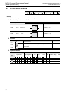
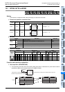
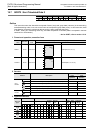
2) Any one of 1 to 4 is specified by n.
In the case of n=0, instruction is not processed.
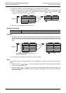
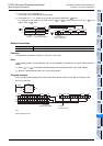
3) In the case of 1 ≤ n ≤ 3, higher (4×(4-n)) bits of the device specified by are 0.
For example, in the case of n=3, lower 4 bits of to ( +2) are stored in b0 to b11 of , and
higher 4 bits of are 0.
Related instructions
Cautions
The instruction is provided in the FX3UC PLC Ver. 2.20 or later.
Error
In the following case, it is an operation error, error flag M8067 is turned ON, and error code is stored in
D8067.
1) When to ( +n) exceeds the device range of the specified devices. (Error code: K6706)
2) When n is specified other than 0 to 4. (Error code: K6706)
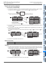
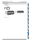
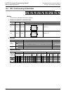
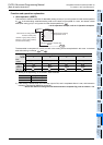
Program example
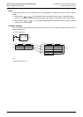
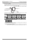
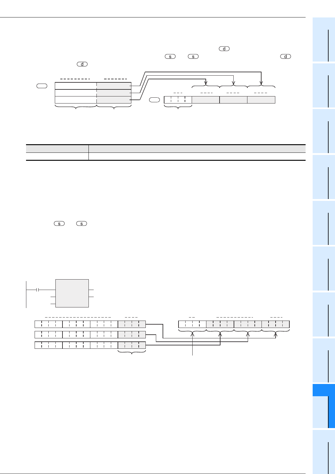
This is a program for coupling lower 4 bits of D0 to D2 when the X000 is turned ON, and storing in D10.
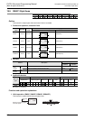
Instruction Content
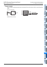
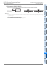
DIS This instruction separates 16-bit data in 4-bit unit.
Lower 4 bits
Lower 4 bits
Lower 4 bits
b15 b4 b3 b0
+0
+1
+2
Ignored.
Data to be coupled
b15 b12b11 b8 b7 b4 b3 b0
In the case of n=3,
b12 to b15 are 0.
0000
d
s
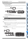
[Structured ladder/FBD]
UNIP
EN
s
n
ENO
d
X000
D0
K3
D10
b15 b4 b3 b0
D0
D1
D2
D10
b15 b12 b11 b4 b3 b0
Data to be coupled
10001010100100001000000000000000
1010000000000000
1001000000000000
0 is set
because n=K3.
[ST]
UNIP(X000,D0,K3,D10);