14 Applied Instructions (External FX I/O Device)
14.2 HKY / Hexadecimal Input
360
FXCPU Structured Programming Manual
[Basic & Applied Instruction]
Cautions
1. Limit of number of times of use of command
Only one of HKY command and DHKY command can be used in the program.
If desired to use plural times, you can program by the index modifier (V, Z) function.
2. When keys are pressed simultaneously
When plural keys are pressed, only the first pressed key is valid
3. When command contact is turned OFF
If turned OFF, the content of is not changed, but all of to +7 are turned OFF.
4. Number of bits occupied
1) To occupy 4 points for connecting 16 keys from the beginning device of input (X).
2) To occupy 4 points for connecting 16 keys from the beginning device of output (Y).
3) To occupy 8 points from beginning device for output of key pushing information.
Be careful not to overlap with the device used in control of the machine.
- to +5 : Key pushing information of keys A to F
- +6 : Key sense output of keys A to F.
- +7 : Key sense output of keys 0 to 9
5. Intake timing of key input
HKY and DHKY commands are executed simultaneously with the operation period of PLC.
At the end of a series of key scan, a time of 8 scans is needed.
To prevent intake error due to filter delay of key input, you can utilize the function of "constant scan mode" or
"timer interruption."
6. Output format
Select and use the PLC of transistor output type.
7. Some restrictions to applicable devices.
S1: The FX3U and FX3UC PLCs only are applicable.
However, index modifier (V, Z) is not applicable.
S2: The FX
3U and FX3UC PLCs only are applicable.
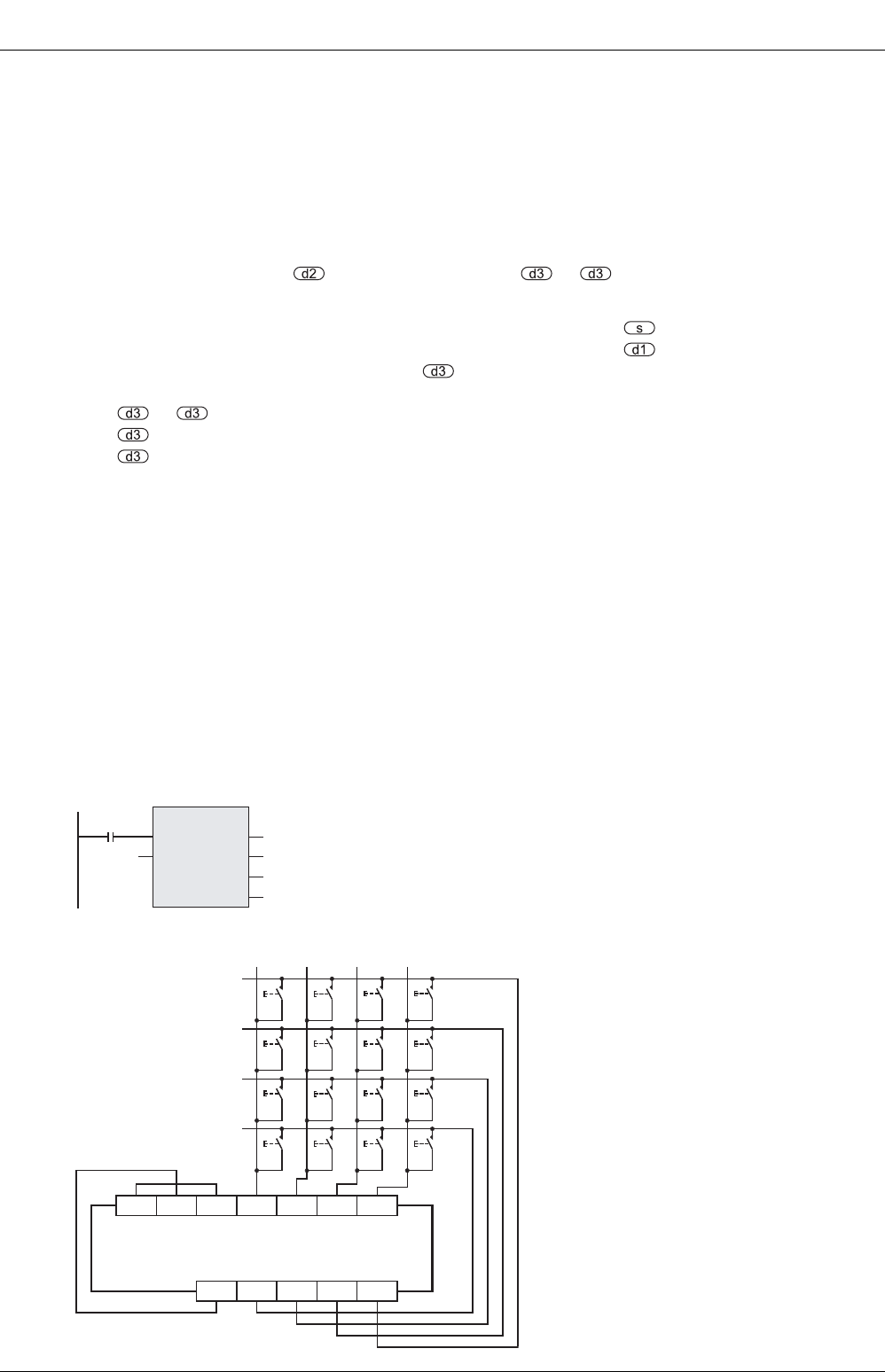
Program examples
The wiring diagram below is an example of basic unit (sync input/sync output) of FX3U series.
For the actual wiring connection, see the manual of the PLC.
X004
HKY
EN
s
ENO
d1
d2
d3
X000
Y000
D0
M0
[Structured ladder/FBD]
[ST]
HKY(X004, X000, Y000, D0, M0);
S/S X000 X001 X002 X003
COM1 Y000 Y001 Y002 Y003
0 1 23
4567
89AB
C DEF
External wiring
Transistor output
PLC
24V 0V


