


20 Applied Instructions (Positioning Control)
20.1 DSZR / Dog Search Zero Return
519
FXCPU Structured Programming Manual
[Basic & Applied Instruction]
11
Applied Instructions
(Data Operation)
12
Applied Instructions
(High Speed
Processing)
13
Applied Instructions
(Handy
Instruction)
14
Applied Instructions
(External FX I/O
Device)
15
Applied Instructions
(External Device
(optional device))
16
Applied Instructions
(External Device)
17
Applied Instructions
(Data Transfer 2)
18
Applied Instructions
(Floating Point)
19
Applied Instructions
(Data Operation 2)
20
Applied Instructions
(Positioning
Control)
Cautions
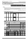
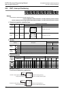
1) Some restrictions to applicable devices.
S1: The FX
3U and FX3UC PLCs only are applicable, index (V, Z) decoration is disabled.
S2: Please specify X000 to X007, in the case of FX
3G, FX3GC, FX3U and FX3UC PLCs.
Please specify X000 to X005, in the case of FX
3S PLC.
S3: Please specify Y000, Y001, Y002
*1
of transistor output of basic unit, or Y000, Y001, Y002
*3
, Y003
*3
of high speed output special adapter
*2
.
*1. The pulse output destination Y002 is not available in FX
3S, FX3G (14-point and 24-point type)
and FX
3GC PLCs.
*2. High speed output special adapter can be connected only in FX
3U PLC.
*3. When using Y002, Y003 in high speed output special adapter, a second high speed output
special adapter is needed.
Points
• When using FX3U PLC of relay output type or triac output type, high speed output special adapter
is needed.
• The output of high speed output special adapter is a differential line driver.
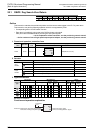
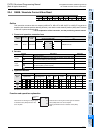
S4: When high speed output special adapter is used at the pulse output destination in the FX
3U PLC, as
the rotating direction signal, use the output shown in the table below.
When built-in transistor output is used at the pulse output destination in the FX
3S, FX3G, FX3GC,
FX
3U and FX3UC PLCs, as the rotating direction signal, use the transistor output.
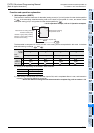
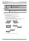
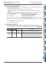
2) Output number of rotating direction signal
Operation changes as follows depending on polarity of output pulse frequency.
[+ (Positive)] → : ON
[- (Negative)] → : OFF
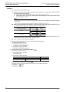
Cautions about writing during RUN
Avoid writing during RUN after either of the following operations in a circuit block including the pulse output
instruction or positioning instruction.
• Changing a program for a circuit block including a corresponding instruction.
• Changing a program for a circuit block just before or after a circuit block including a corresponding
instruction.
• Deleting or adding a circuit block just before or after a circuit block including a corresponding instruction.
This caution about the above operations is applicable to the following PLCs and instructions.
FX
1S, FX1N and FX1NC PLCs : PLSY, DPLSY, PWM, PLSR, DPLSR, ZRN, DZRN, PLSV,
DPLSV,DRVI, DDRVI, DRVA and DDRVA
FX
2N and FX2NC PLCs : PLSY, DPLSY, PWM, PLSR and DPLSR
FX
3S, FX3G, FX3GC, FX3U and FX3UC PLCs: DSZR, DVIT
*1
, DDVIT
*1
, DTBL
*2
, ZRN, DZRN, PLSV, DPLSV,
DRVI, DDRVI, DRVA and DDRVA
Note that the pulse output will decelerate and stop when writing during RUN is executed in the FX
3S, FX3G,
FX
3GC, FX3U or FX3UC PLC.
*1. Not available for the FX
3S, FX3G or FX3GC PLC.
*2. Not available for the FX
3S PLC.
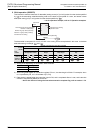
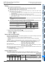
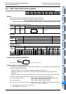
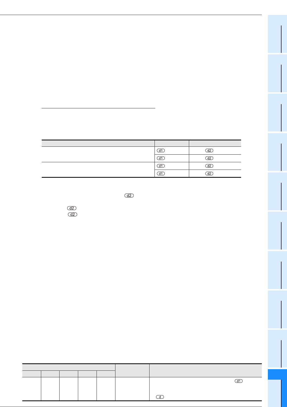
Function changes by version
This instruction includes the function changes as shown in the table below depending on the version.
→ As for the explanation of the instruction and contents of function changes, refer to the positioning
control manual.
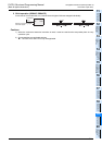
Connection position of high speed output special adapter Pulse output Rotating direction signal
First unit
=Y000 =Y004
=Y001 =Y005
Second unit
=Y002 =Y006
=Y003 =Y007
Corresponding version
Item Outline of function
FX3S FX3G FX3GC FX3U FX3UC
Ver. 1.00
or later
Ver. 1.00
or later
Ver. 1.40
or later
Ver. 2.20
or later
Ver. 2.20
or later
Clear signal
output destination
designating
function
When special auxiliary relay corresponding to is turned
ON, the clear signal output specification is changed to the
output number specified by special data register corresponding
to