


12 Applied Instructions (High Speed Processing)
309
FXCPU Structured Programming Manual
[Basic & Applied Instruction]
11
Applied Instructions
(Data Operation)
12
Applied Instructions
(High Speed
Processing)
13
Applied Instructions
(Handy
Instruction)
14
Applied Instructions
(External FX I/O
Device)
15
Applied Instructions
(External Device
(optional device))
16
Applied Instructions
(External Device)
17
Applied Instructions
(Data Transfer 2)
18
Applied Instructions
(Floating Point)
19
Applied Instructions
(Data Operation 2)
20
Applied Instructions
(Positioning
Control)
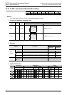
12.10 PLSR / Acceleration/Deceleration Setup
•For FX3U and FX3UC PLCs :16-bit instruction→10 to 32,767(Hz)
32-bit instruction→10 to 100,000 Hz or less
(200,000 Hz or less when using special high speed adapter.)
•For FX3S, FX3G and FX3GC PLCs :16-bit instruction→10 to 32,767(Hz)
32-bit instruction→10 to 100,000 Hz or less
•For FX
2N and FX2NC PLCs :10 to 20,000 Hz
•For FX
1S and FX1N PLC :10 to 100,000 Hz
•For FX
1NC PLC :10 to 10,000 Hz
2. Total number of output pulses
Set the total number of output pulses specified by as follows.
•For FX
3U and FX3UC PLCs :16-bit instruction→1 to 32,767PLS
32-bit instruction→1 to 2,147,483,647PLS
•For FX
3S, FX3G and FX3GC PLCs :16-bit instruction→1 to 32,767PLS
32-bit instruction→1 to 2,147,483,647PLS
•For FX
2N and FX2NC PLCs :16-bit instruction→110 to 32,767PLS
32-bit instruction→110 to 2,147,483,647PLS
When setting a value less than "110", the operation is as follows.
PLC version V3.00 or before : The pulses are not generated normally.
PLC version V3.00 or later : One tenth of the maximum frequency is generated.
If the maximum frequency is 100 Hz or less, "10 Hz" is generated.
•For FX
1S, FX1N and FX1NC PLCs : 16-bit instruction→110 to 32,767(PLS)
32-bit instruction→110 to 999,999(PLS)
When setting a value less than "110", the pulses are not generated normally.
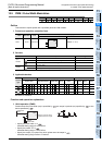
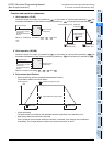
3. Acceleration/deceleration time
Set the acceleration/deceleration time specified by as follows.
For FX
3S, FX3G, FX3GC, FX3U and FX3UC PLCs: 50 to 5000 (ms)
For FX
2N and FX2NC PLCs: 5000 (ms) or less
Follow, however, the conditions a) through d).
a) Make the acceleration/deceleration time be 10 times or more the PLC's maximum scan time (value of
D8012 or greater). If set to less than 10 times, the acceleration/deceleration timing becomes instable.
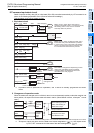
b) The following equation defines the allowable minimum that can be set as the acceleration/
deceleration time.
If setting a value less than the equation indicates, the error in the acceleration time becomes large. If
set to less than "90000/ , operation takes place while rounding it up to "90000/ ".
c) The following equation defines the allowable maximum that can be set as the acceleration/
deceleration time.
d) The number of speed changes (steps) for the acceleration/deceleration is fixed to "10 times" as shown
in the previous page.
If unable to set the PLC to these conditions, lower the maximum frequency specified by .
•For FX1S, FX1N and FX1NC PLCs: 50 to 5000(ms)
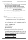
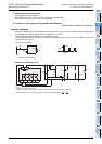
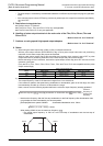
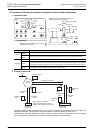
4. Pulse output
• Only a transistor output on the main unit or Y000 or Y001 on a special high speed output adapter
*1
can be
specified in .
*1. Special high speed output adapters can be connected only to the FX
3U PLC.
When using the PLSR instruction with a relay output type or triac output type FX
3U PLC, a special
highspeed output adapter is required.
• The duty cycle of the pulse ON/OFF time is 50 % inside the PLC.
However, 50 % may not be output depending on the frequency due to the effect of the output circuit.
90000
s1
s3
5
≥
×
≤
×
s1
s3
818
s2