


29 Applied Instructions (Data Table Operation)
29.3 ZONE / Zone Control
689
FXCPU Structured Programming Manual
[Basic & Applied Instruction]
21
Applied Instructions
(Real Time
Clock Control)
22
Applied Instructions
(External Device)
23
Applied Instructions
(Extension
Function)
24
Applied Instructions
(Others)
25
Applied Instructions
(Block Data
Operation)
26
Applied Instructions
(Character
String Control)
27
Applied Instructions
(Data Operation 3)
28
Applied Instructions
(Data Comparison)
29
Applied Instructions
(Data Table
Operation)
30
Applied Instructions
(External Device
Communication)
Cautions
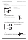
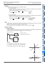
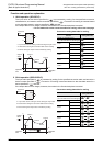
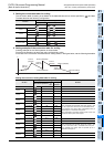
1) When the output value overflows, it is handled as follows:
a) In the 16-bit operation
The output value is a 16-bit binary value with sign. Accordingly, if the operation result is outside the
range from -32768 to 32767, it is handled as follows:
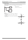
b) In the 32-bit operation
The output value is a 32-bit binary value with sign. Accordingly, if the operation result is outside the
range from -2,147,483,648 to 2,147,483,647, it is handled as follows:
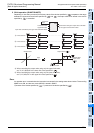
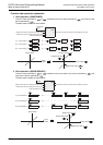
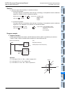
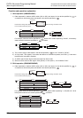
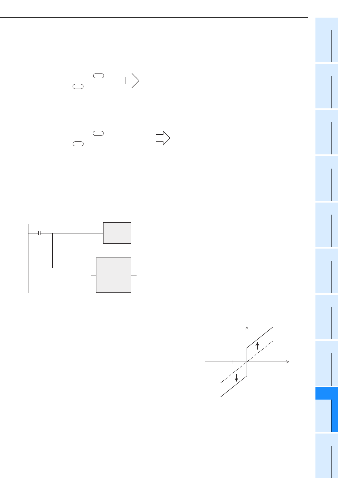
Program example
1. Program example 1
In the program example shown below, the BCD data set in X020 to X037 is controlled by the zone from
"-1000" to "1000", and the controlled value is output to D1 when X000 turns ON.
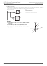
Operation
1) In the case of "D0 < 0", "D0 + (-1000)" is output to D1.
2) In the case of "D = 0", "0" is output to D1.
3) In the case of "0 < D0", "D0 + 1000" is output to D1.
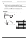
Negative bias value =-100
s1
Input value =-32,768
s3
Output value =-32,768+(-100)
=8000H+FF9CH
=7F9CH
=32,668
Negative bias value =-1000
Input value =-2,147,483,648
Output value
s1
s3
=-2,147,483,648+(-1000)
=80000000H+FFFFFC18H
=7FFFFC18
=2,147,482,648
X000
BIN
EN
s
ENO
d
K4X020 D0
ZONEP
EN ENO
d
s1
s2
s3
K-1000
K1000
D0
D1
[Structured ladder/FBD] [ST]
BIN(X000,K4X020,D0);
ZONEP(X000,K-1000,K1000,D0,D1);
Input
0
Output
1000
-1000
1000
-1000