


12 Applied Instructions (High Speed Processing)
300
FXCPU Structured Programming Manual
[Basic & Applied Instruction]
12.8 PLSY / Pulse Y Output
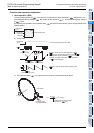
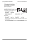
6. Handling of pulse output terminals in the main units
The outputs Y000 and Y001 are the high speed
response type.
When using a pulse output instruction or
positioning instruction, adjust the load current of
the open collector transistor output.
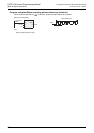
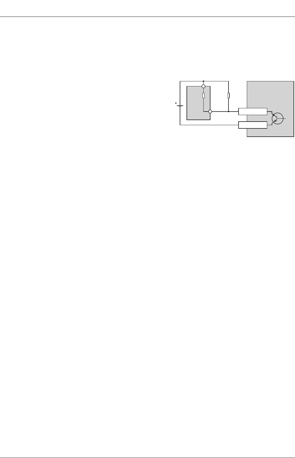
When the load is smaller, connect a dummy
resistor in parallel to the outside of a used output
terminal (Y000 or Y001) as shown in the circuit
diagram below so that the specified current shown
below flows in the output transistor.
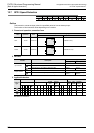
1) For FX
3S
, FX
3G
, FX
3GC
, FX
3U
and FX
3UC
PLCs
Operating voltage range : DC5 to 24V
Operating current range : 10 to 160 mA
Output frequency : 100 kHz or less
2) For FX
2N and FX2NC PLCs
Operating voltage range : DC5V Operating voltage range : DC12 to 24V
Operating current range : 0.1A Operating current range : 0.1A
Output frequency : 20 kHz or less Output frequency : 10 kHz or less
3) For FX
1NC PLC
Operating voltage range : DC5V Operating voltage range : DC12 to 24V
Operating current range : 10 to 100 mA Operating current range : 50 to 100 mA
Output frequency : 10 kHz or less Output frequency : 10 kHz or less
4) For FX
1S and FX1N PLCs
Even without connecting a dummy resistor, a pulse output of 100 kHz or less can be generated under 5 to
24 VDC (10 to 100 mA).
5) For FX
0S, FX0, FX0N, FXU and FX2C PLCs
Have a current of about 100 mA flow for the FX
2C PLC and a current of about 200 mA flow for the FX0S,
FX
0, FX0N and FXU PLCs and extension.
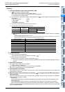
External
power
supply
Equipment
load
resistor
Dummy
resistor
Y000
COM1
PLC
(transistor output)
[sink output]
Input circuit