


12 Applied Instructions (High Speed Processing)
305
FXCPU Structured Programming Manual
[Basic & Applied Instruction]
11
Applied Instructions
(Data Operation)
12
Applied Instructions
(High Speed
Processing)
13
Applied Instructions
(Handy
Instruction)
14
Applied Instructions
(External FX I/O
Device)
15
Applied Instructions
(External Device
(optional device))
16
Applied Instructions
(External Device)
17
Applied Instructions
(Data Transfer 2)
18
Applied Instructions
(Floating Point)
19
Applied Instructions
(Data Operation 2)
20
Applied Instructions
(Positioning
Control)
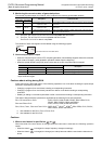
12.9 PWM / Pulse Width Modulation
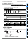
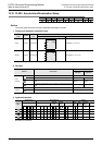
3. Restrictions to target devices
S1: Refer to item 2 of "Cautions".
S2: The FX
3G, FX3GC, FX3U and FX3UC PLCs only are applicable.
S3: The FX
3U and FX3UC PLCs only are applicable.
4. Cautions on using special high speed output adapters
→ Refer to item in section 12.9 "Cautions".
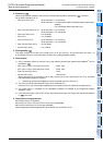
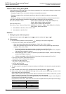
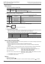
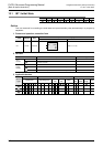
Program examples
When the contents of D10 are changed in the range from "0" to "50" in the program example shown below,
the average output from Y000 will be in the range from 0 to 100%.
When the contents of D10 exceed "50", it becomes an error.
In this program example, the FX
3U series main unit (sink output) is used. For wiring details, refer to the
manual of the PLC used.
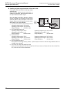
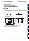
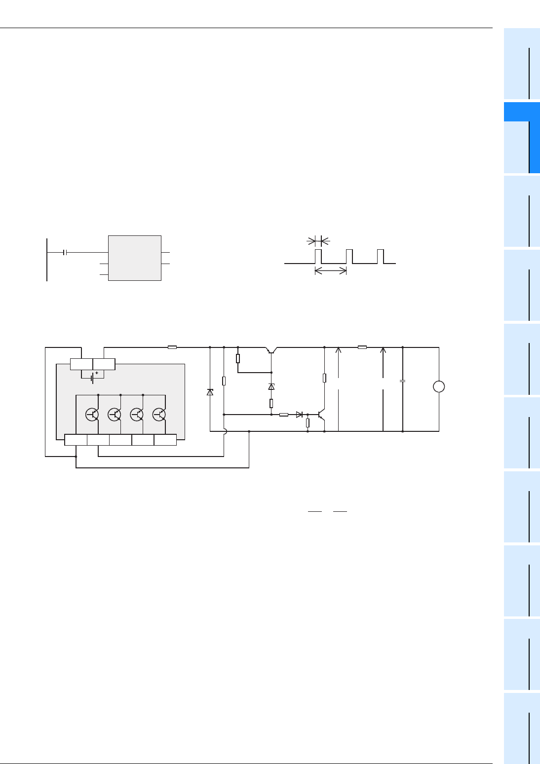
Example of smoothing circuit
X0
D10
50ms
Y000
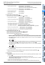
PWM
EN
s1
s2
ENO
d
D10
K50
Y000
[ST]
PWM(X0,D10,K50,Y000);
[Structured ladder/FBD]
Y000
COM1
Y001 Y002 Y003
PLC
510Ω
12V
1kΩ
1kΩ
1kΩ
1kΩ
P
22Ω
E
R
(1kΩ
τ
×
τ
τ
≤
)
e
V
+
C
470µF
10V
5V
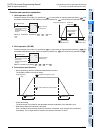
R>>P
=R(k ) C(µF)=470ms>>To
The time constant of the filter should be considerably larger than the pulse cycle T0.
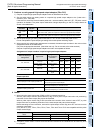
The ripple value " e" in the mean output current "e" is approximately " ".
e
Δ
e
Δ
To
0V 24V
Ω