


14 Applied Instructions (External FX I/O Device)
14.3 DSW / Digital Switch (Thumbwheel Input)
362
FXCPU Structured Programming Manual
[Basic & Applied Instruction]
Function and operation explanation
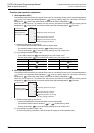
1. 16-bit operation(DSW)
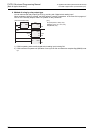
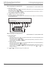
The value of digital switch connected to the device designated in is processed by time division (entered
sequentially from the first digit by output signals at 100 ms intervals), and stored in the device designated in
.
1) Data
- You can read up to 4 digits from 0 to 9,999.
- Data is stored in BIN (binary value).
- First set is stored in , and second set in +1.
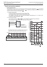
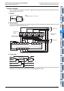
2) Designation of number of sets n
- When using 4 digits and 1 set × 1 (n=K1)
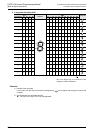
Digital switch of 4 digits in BCD connected to to +3 is sequentially read in by strobe signals
to +3, and stored in as BIN value.
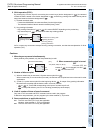
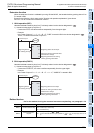
- When using 4 digits and 1 set × 2 (n=K2)
Digital switch of 4 digits in BCD connected to to +3 is sequentially read in by strobe signals
to +3, and stored in as BIN value.
- Digital switch of 4 digits in BCD connected to +4 to +7 is sequentially read in by strobe signals
to +3, and stored in +1 as BIN value.
Related devices
→ As for the method of using the command execution complete flag, see paragraph 1.3.4.
Cautions
1. When command contact is turned OFF
If turned OFF, the content of is not changed, but all of to +3 are turned OFF.
2. Number of bits occupied
1) When 4 digits and 2 sets (n=K2) are used, 2 points are occupied from .
2) occupies 4 points in the case of 4 digits and 1 set, and occupies 8 points in the case of 4 digits and
2 sets.
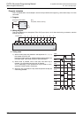
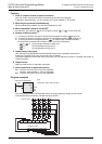
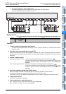
3. When connecting a digital switch of less than 4 digits
The wiring of strobe signal <output for digit designation> is not needed in the digit not in use, but the
output for digit not in use is occupied by this command, and cannot be used in other application. The output
not in use must be always kept vacant.
4. We recommend to use the transistor output type.
To take in the values of digital switch continuously, you must use the PLC of transistor output.
→ As for the relay output type, refer to the "Method of using by relay output type" shown later.
5. Digital switch
Use the digital switch of BCD output.
6. Some restrictions to applicable devices.
S1: The FX3G, FX3GC, FX3U and FX3UC PLCs only are applicable.
S2: The FX
3U and FX3UC PLCs only are applicable.
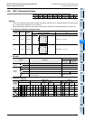
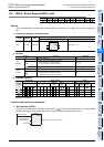
Device Name Content
M8029
Command execution
complete
OFF : Scan continuous or command not executed from to +3.
ON : ON after one-cycle operation of to +3 output (scan of 1 to 4 digits)
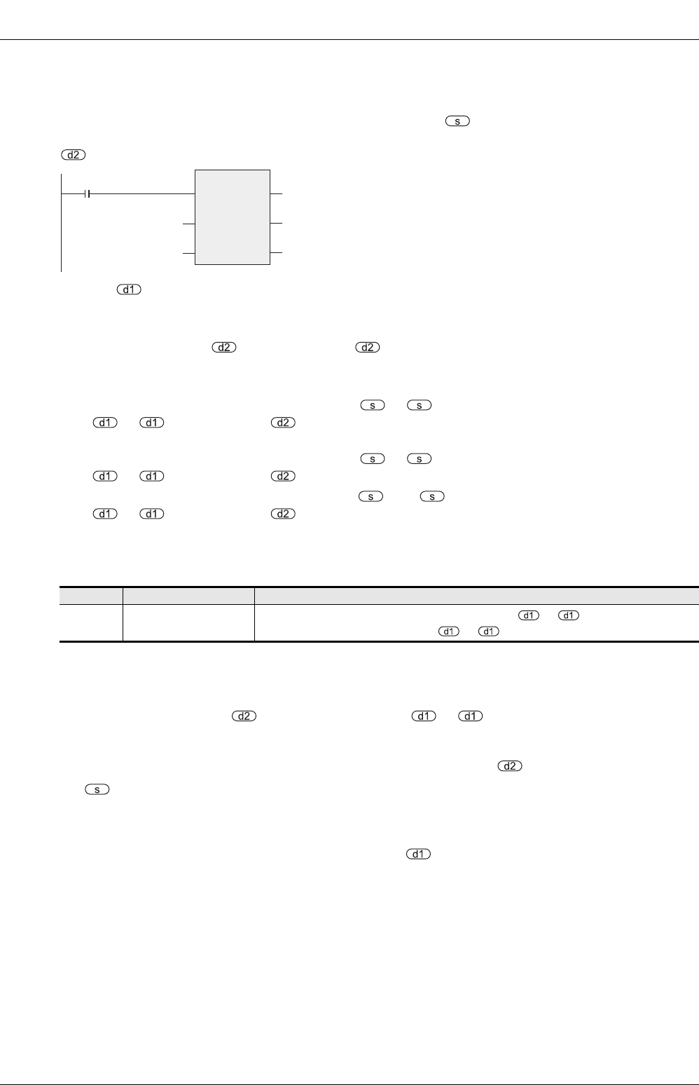
Command input
Beginning device of strobe signal output
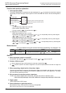
DSW
EN
s
ENO
d1
d2
Device for storing the numerical value of
digital switch
Beginning device for
connecting digital switch
Number of sets of digital
switches
n