


35 Interrupt Function and Pulse Catch Function
813
FXCPU Structured Programming Manual
[Basic & Applied Instruction]
31
Applied Instructions
(Data Transfer 3)
32
Applied Instructions
(High Speed
Processing 2)
33
Applied Instructions
(Extension File
Register Control)
34
Applied Instructions
(FX
3U
-CF-ADP)
35
Interrupt Function
and Pulse Catch
Function
A
Relationships
between devices
and addresses
B
Applied
Instruction List
35.8 Pulse width/Pulse period measurement function [M8075 to M8083, D8074 to D8097]
35.8 Pulse width/Pulse period measurement function [M8075 to M8083,
D8074 to D8097]
This function is supported only in FX3G PLC (Ver.1.10 or later) and FX3GC.
The pulse width/pulse period measurement function stores the values of 1/6 μs ring counters at the input
signal rising edge and falling edge to special data registers. This function also divides by "60" the difference in
the counter value (pulse width) between the rising edge and the falling edge or the difference in the counter
value (pulse period) between the previous rising edge and the current rising edge, and stores the obtained
pulse width or pulse period in units of 10 μs to special data registers.
The pulse width/pulse period measurement function becomes valid when a program is described using
M8075 as a contact. Specify the pulse width measurement flag in the subsequent OUT instruction, and set an
input terminal to be used.
When the pulse width/pulse period measurement function is valid, it always operates while the PLC mode is
RUN.
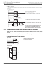
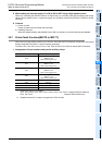
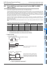
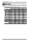
Assignment of special auxiliary relays and special data registers
*1. Cleared when the PLC mode switches from STOP to RUN.
*2. The measurable pulse width is 10 μs minimum and 100 s maximum.
The measurable pulse period is 20 μs minimum and 100 s maximum.
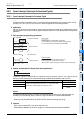
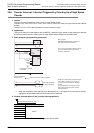
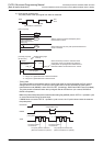
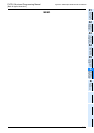
1. Program example
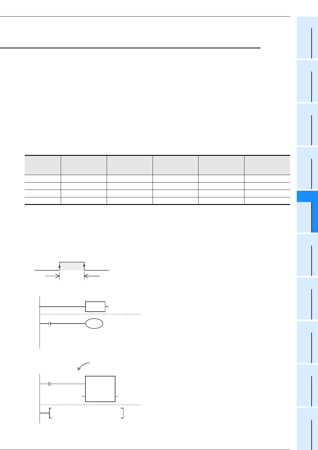
1) Pulse width measurement
The pulse width of the input signal from X000 is measured.
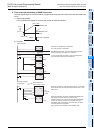
Pulse input
Pulse width/ Pulse
period measurement
flag
Pulse period
measurement mode
Ring counter value
for rising edge
*1
[Unit: 1/6 μs]
Ring counter value
for falling edge
*1
[Unit: 1/6 μs]
Pulse width /Pulse
period
*1*2
[Unit: 10 μs]
X000 M8076 M8080 D8075, D8074 D8077, D8076 D8079, D8078
X001 M8077 M8081 D8081, D8080 D8083, D8082 D8085, D8084
X003 M8078 M8082 D8087, D8086 D8089, D8088 D8091, D8090
X004 M8079 M8083 D8093, D8092 D8095, D8094 D8097, D8096
This duration is measured.
ON
OFF
X000
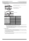
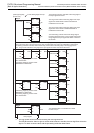
EN ENO
EI
DMOV
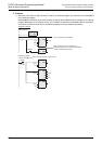
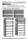
[Main program]
[Interrupt program]
(Event: I000)
X000 Falling edge
interrupt
*1. VAR_01 is a global label and is defined as D8078.
*2. VAR_02 is a global label and is defined as D0.
X000 is used for the pulse width/pulse period
measurement function.
When the interrupt routine is executed at the
falling edge of the input signal from X000, the
pulse width of input signal from X000 stored in
D8078 and D8079 is transferred to D1 and D0.
M8075
M8000
RUN monitor
VAR_01
*1
VAR_02
*2
Pulse width/Pulse
period measurement
setting flag
M8076
EN ENO
sd
User program