


15 Applied Instructions (External Device (optional device))
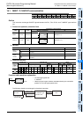
15.8 RS2 / Serial Communication 2
413
FXCPU Structured Programming Manual
[Basic & Applied Instruction]
11
Applied Instructions
(Data Operation)
12
Applied Instructions
(High Speed
Processing)
13
Applied Instructions
(Handy
Instruction)
14
Applied Instructions
(External FX I/O
Device)
15
Applied Instructions
(External Device
(optional device))
16
Applied Instructions
(External Device)
17
Applied Instructions
(Data Transfer 2)
18
Applied Instructions
(Floating Point)
19
Applied Instructions
(Data Operation 2)
20
Applied Instructions
(Positioning
Control)
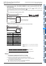
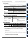
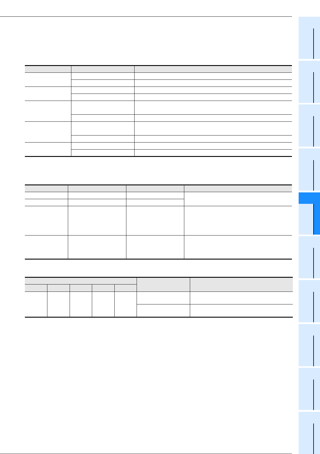
System configuration
In order to use this instruction, you must install any one of the following products in the basic unit.
→ As for the system configuration, refer to the hardware manual of the corresponding
PLC main unit.
→ As for the detailed explanation, refer to the communication control manual.
*1. Required to use ch0 (standard built-in RS-422 port) in FX
3G and FX3GC PLCs.
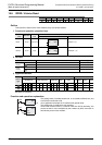
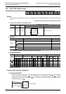
Difference between RS instruction and RS2 instruction
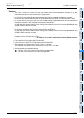
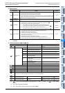
Function change by version
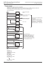
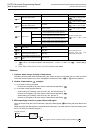
Cautions
→ As for other cautions, refer to the communication control manual.
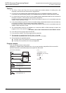
1) With RS, RS2 instructions, do not drive the same port simultaneously by plural instructions.
2) It is not permitted to use an "RS or RS2" instruction and a following instruction for the same port:
- "IVCK, IVDR, IVRD, IVWR, IVBWR
*1
or IVMC" instruction
- "ADPRW" instruction
-"FLCRT
*1
, FLDEL
*1
, FLWR
*1
, FLRD
*1,
FLCMD
*1
or FLSTRD
*1
" instruction
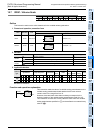
3) When using the header or terminator, please set the data of the header or terminator in the special D
before driving the RS2 instruction. Do not change the values of the header or terminator during driving of
RS2 instruction.
4) Some restrictions to applicable devices.
S1: The FX
3G, FX3GC, FX3U and FX3UC PLCs only are applicable.
*1. The instruction is not provided in the FX
3S, FX3G and FX3GC PLCs.
PLC Type of communication Option
FX3U,
FX3UC-32MT-LT(-2)
RS-232C communication FX3U-232-BD or FX3U-232ADP(-MB)
RS-485 communication FX3U-485-BD or FX3U-485ADP(-MB)
FX3UC(D, DS, DSS)
RS-232C communication FX3U-232ADP(-MB)
RS-485 communication FX3U-485ADP(-MB)
FX3G
RS-232C communication
FX3G-232-BD or FX3U-232ADP(-MB) (FX3G-CNV-ADP is needed)
RS-232C/RS-422 converter
*1
(FX-232AW, FX-232AWC and FX-232AWC-H)
RS-485 communication FX3G-485-BD(-RJ) or FX3U-485ADP(-MB) (FX3G-CNV-ADP is needed)
FX3GC
RS-232C communication
FX3U-232ADP(-MB)
RS-232C/RS-422 converter
*1
(FX-232AW, FX-232AWC and FX-232AWC-H)
RS-485 communication FX3U-485ADP(-MB)
FX3S
RS-232C communication FX3G-232-BD or FX3U-232ADP(-MB) (FX3S-CNV-ADP is needed)
RS-485 communication FX3G-485-BD(-RJ) or FX3U-485ADP(-MB) (FX3S-CNV-ADP is needed)
Item RS2 instruction RS instruction Remarks
Header size 1 to 4 characters (bytes) Up to 1 character (byte)
For the RS2 instruction, up to 4 characters (bytes) can
be specified as a header or terminator.
Terminator size 1 to 4 characters (bytes) Up to 1 character (byte)
Attachment of check
sum
The check sum can be
automatically attached.
The check sum should be
attached by a user program.
For the RS2 instruction, the check sum can be
automatically attached to the sent and received data.
In this case, however, make sure to use a terminator
with the communication frame to be sent and
received.
Used channel
number
ch0, ch1, ch2 ch1
For the RS2 instruction:
Ch0 is applicable to FX3G and FX3GC PLCs only.
In the case of FX3S and FX3G (14-point and 24-point
type) PLCs, ch2 cannot be used.
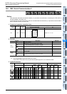
Corresponding version
Item Outline of function
FX3S FX3G FX3GC FX3U FX3UC
Ver. 1.00
or later
Ver. 1.00
or later
Ver. 1.40
or later
Ver. 2.30
or later
Ver. 2.30
or later
ch1
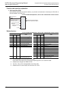
Data set ready (DSR) flag
When DR (DSR) signal of ch1 is ON, special device
M8405 is turned ON.
ch2
Data set ready (DSR) flag
When DR (DSR) signal of ch2 is ON, special device
M8425 is turned ON.