


16 Applied Instructions (External Device)
16.4 RMST / F2-32RM start
424
FXCPU Structured Programming Manual
[Basic & Applied Instruction]
16.4 RMST / F2-32RM start
Outline
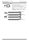
This instruction gives start signal from the PLC or receives status information, in the F2-32RM type
programmable cam switch.
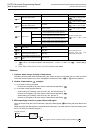
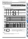
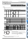
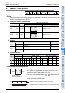
1. Format and operation, execution form
2. Set data
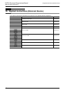
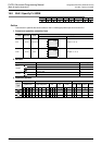
3. Applicable devices
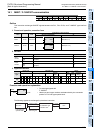
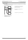
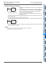
Function and operation explanation
• This instruction gives start command from the PLC or receives status
information, in the F
2-32RM type programmable cam switch.
• The content of the device specified by , is determined by the
connection position of FX
2-24EI type special adapter.
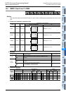
• In the device specified by , the status information is stored as
follows.
As for the meaning of each status, please refer to the user's manual of F
2-32RM type programmable cam
switch.
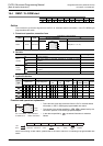
FX3U(C) FX3G(C) FX3S FX2N(C) FX1N(C) FX1S FXU/FX2C FX0N FX0(S)
Instruction
name
Operation
Execution
form
Expression in each language
Structured ladder/FBD ST
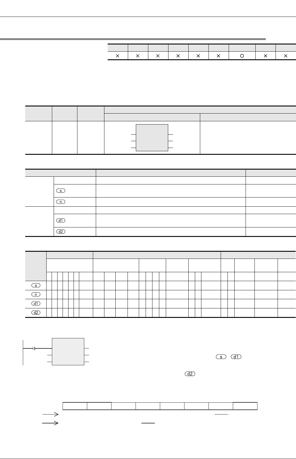
RMST 16 bits Continuous RMST(EN, s, n, d1, d2);
Variable Description Data type
Input
variable
EN Execution condition Bit
Head input number of FX2-24EI connected to F2-32RM (16 points
occupied)
Bit
Program (bank) number of F2-32RM (n = 0, 1). ANY16
Output
variable
ENO Execution state Bit
Head output number of FX2-24EI connected to F2-32RM (8 points
occupied)
Bit
Head of device storing status information (8 points occupied) Bit
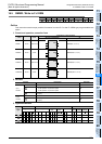
Operand
type
Bit Devices Word Devices Others
System user Digit designation
System
user
Special
unit
Index
Con
stant
Real
Number
Character
String
Pointer
XYMTCS
D
.b
KnX KnY KnM KnS T C D R
U\G
V Z Modifier K H E
"
"
P
z
zz
z
zz z z
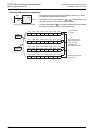
RMST
EN
s
n
ENO
d1
d2
X000
FXU→FX2-32RM Start command
F
2-32RM→FXU Status information
Y030X040
RMST
EN
s
n
ENO
d1
d2K0 M300
M307 M306 M305 M304 M303 M302 M301 M300
Normal Normal
CW
Normally
ON
1.0° START
BANK1
S/W error H/W error
CCW 0.5° STOP
Normally
OFF
BANK0
ON
OFF