


35 Interrupt Function and Pulse Catch Function
807
FXCPU Structured Programming Manual
[Basic & Applied Instruction]
31
Applied Instructions
(Data Transfer 3)
32
Applied Instructions
(High Speed
Processing 2)
33
Applied Instructions
(Extension File
Register Control)
34
Applied Instructions
(FX
3U
-CF-ADP)
35
Interrupt Function
and Pulse Catch
Function
A
Relationships
between devices
and addresses
B
Applied
Instruction List
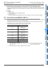
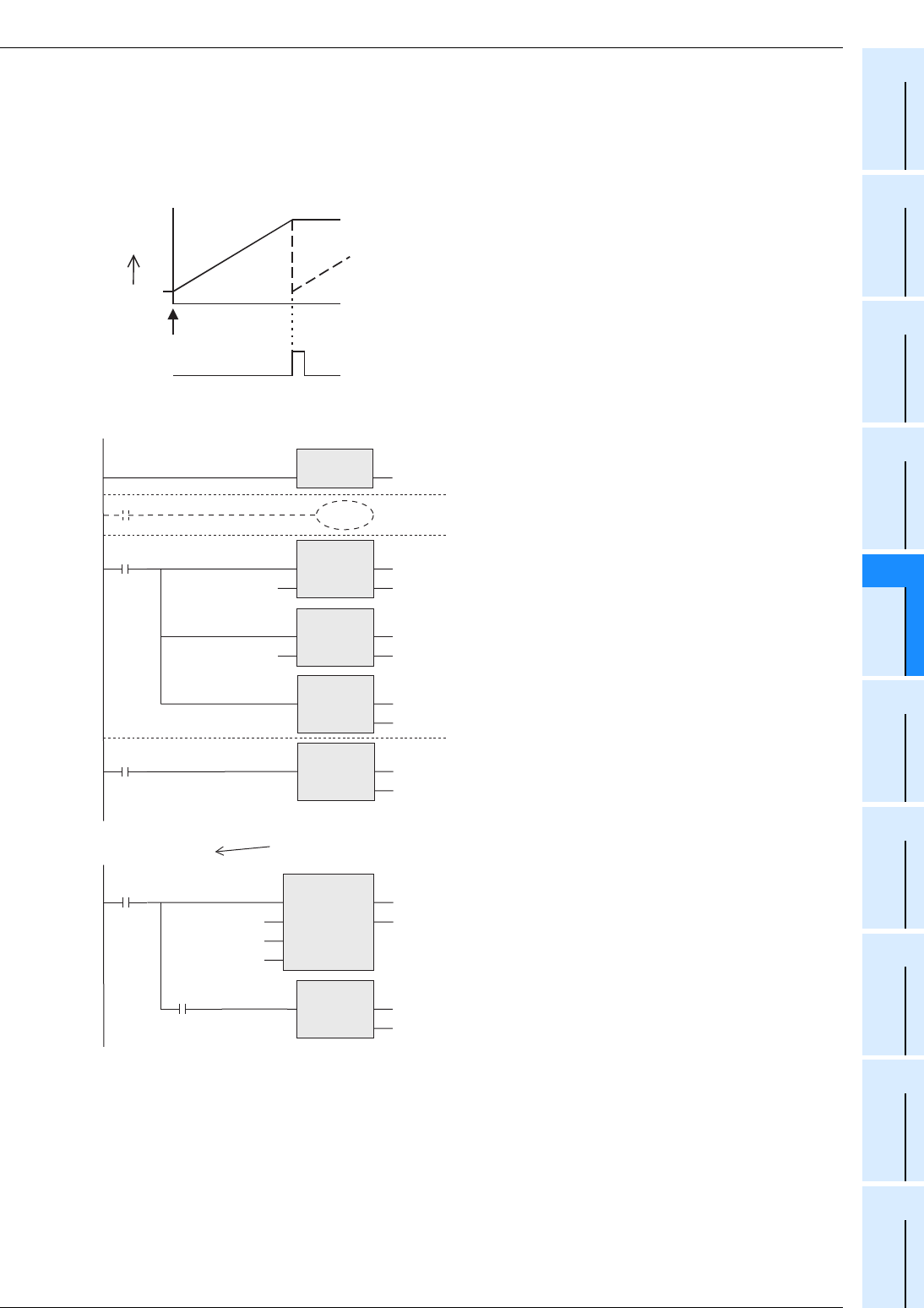
35.5 Timer Interrupt (Interrupt in Constant Cycle)
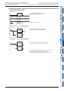
2. Timer interrupt processing of RAMP instruction
The ramp signal output circuit shown below is programmed using the timer interrupt function executed every
10 ms.
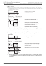
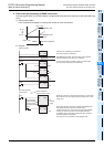
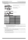
1) Ramp output pattern
D4 is occupied as a register for counting the number of times of execution.
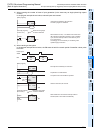
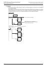
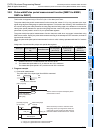
2) Program
(D 2) = 255
(D 1) = 1
(D 3)
X000 = ON
M8029 Execution completed
While M8026 is OFF
10 seconds
While M8026 is ON
EI
EN ENO
Interrupts are enabled by EI instruction.
The main program is described.
RST
EN ENO
d
When the instruction execution complete flag M8029 turns
ON, RAMP instruction drive input is set to OFF.
If RAMP instruction is continuously executed while M8026
is OFF, the value of D3 returns to the initial value (D1)
immediately after it reaches the final value (D2), and then
the same operation is repeated.
This program is not necessary when M8026 is ON.
SET
EN ENO
d
M1
While the instruction is executed 1000 times (in 10 seconds),
the contents of D3 are changed from the value of D1 to the
value of D2.
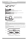
MOV
EN
s
ENO
d
D1
MOV
EN
s
ENO
d
D2
PLS
EN ENO
d
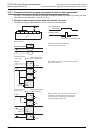
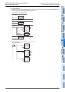
RAMP
EN
s1
s2
ENO
d
n
(Number of times
of transfer)K1000
X000
M1
M8029
(Target value)D2
(Initial value)D1
D3
(Current
value)
M1
M0
K1
K255
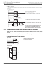
With M8026 turned ON, when the value of (D3) reaches
the final value (D2), the value of Y is latched.
As soon as the start command is given, the initial value
(D1) and target value (D2) are transferred.
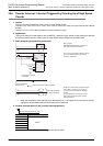
Start
M0
M8026
When interrupt is
given at every 10 ms
[Main program]
[Interrupt program]
(Event: I610)