


30 Applied Instructions (External Device Communication)
30.1 IVCK / Inverter Status Check
709
FXCPU Structured Programming Manual
[Basic & Applied Instruction]
21
Applied Instructions
(Real Time
Clock Control)
22
Applied Instructions
(External Device)
23
Applied Instructions
(Extension
Function)
24
Applied Instructions
(Others)
25
Applied Instructions
(Block Data
Operation)
26
Applied Instructions
(Character
String Control)
27
Applied Instructions
(Data Operation 3)
28
Applied Instructions
(Data Comparison)
29
Applied Instructions
(Data Table
Operation)
30
Applied Instructions
(External Device
Communication)
Function and operation explanation
→ For detailed explanation of the instruction, refer to the Data Communication Edition manual.
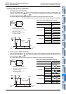
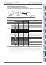
1. 16-bit operation (IVCK)
The operation status corresponding to the instruction code
*1
specified in the device specified by of an
inverter connected to communication port n whose station number is specified in the device specified by
is read and transferred to the device specified by .
*1. Refer to the instruction code list.
Refer to the pages in the inverter manual on which the computer link function is explained in detail.
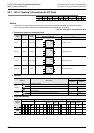
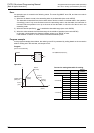
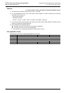
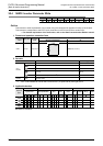
2. Instruction codes of inverters
The table below shows the inverter instruction codes specified in along with their functions.
Only use the instruction codes shown below. Use of instruction codes not shown below may cause
communication errors.
Do not use instruction codes not shown in the table below. They may cause communication errors.
For instruction codes, refer to the pages in the inverter manual where the computer link function is explained
in detail.
*1. Please write "0" to instruction code HFF (Link parameter expansion setting) just before the IVCK
instruction when reading frequency.
When "0" is not written, reading of the frequency may not be executed normally.
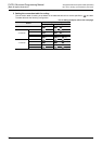
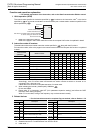
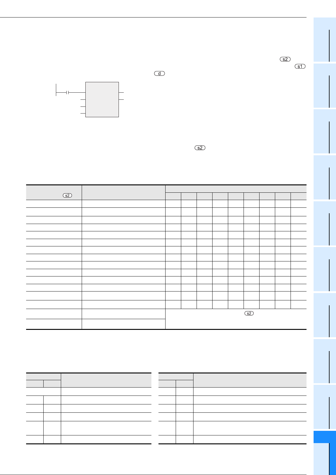
3. Related devices
→ For the instruction execution complete flag use method, refer to Section 1.3.4.
*1. Cleared when PLC power supply is turned from OFF to ON.
*2. Cleared when the PLC mode switches from STOP to RUN.
*3. Initial value: -1
Instruction code
specified in
Read contents
Corresponding inverter
F700 A700 E700 D700 V500 F500 A500 E500 S500
H7B Operation mode 333333333
H6F Output frequency (number of rotations) 3333
3
*1
3333
H70 Output current 333333333
H71 Output voltage 33333333 -
H72 Special monitor 3333333 --
H73 Special monitor selection number 3333333 --
H74 Abnormal contents 333333333
H75 Abnormal contents 333333333
H76 Abnormal contents 33333333 -
H77 Abnormal contents 33333333 -
H79 Inverter status monitor (extension) 3333 -----
H7A Inverter status monitor 333333333
H6E Set frequency (read from E2PROM) 3333
3
*1
3333
H6D Set frequency (read from RAM) 3333
3
*1
3333
H7F Link parameter extended setting
These codes cannot be specified in of the IVCK instruction.
They are automatically processed when a "second parameter
specification code" is specified the IVRD instruction.
H6C Second parameter changing
Number
Description
Number
Description
ch1 ch2 ch1 ch2
M8029 Instruction execution complete D8063 D8438
Error code of serial communication error
*1
M8063 M8438
Serial communication error
*1
D8150 D8155
Response wait time in inverter communication
*1
M8151 M8156 Inverter communicating D8151 D8156
Step number in inverter communication
*3
M8152 M8157
Inverter communication error
*2
D8152 D8157
Error code of inverter communication error
*2
M8153 M8158
Inverter communication error latch
*2
D8153 D8158
Latch of inverter communication error occurrence
step
*2*3
M8154 M8159
IVBWR instruction error
*2
D8154 D8159
IVBWR instruction error parameter number
*2*3
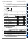
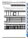
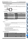
IVCK
EN ENO
d
s1
s2
n
Command
input
Inverter station number
Inverter instruction code
Channel to be used
Device storing the read value