


28 Applied Instructions (Data Comparison)
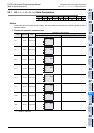
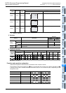
28.1 LD =, >, <, <>, <=, >= / Data Comparison
671
FXCPU Structured Programming Manual
[Basic & Applied Instruction]
21
Applied Instructions
(Real Time
Clock Control)
22
Applied Instructions
(External Device)
23
Applied Instructions
(Extension
Function)
24
Applied Instructions
(Others)
25
Applied Instructions
(Block Data
Operation)
26
Applied Instructions
(Character
String Control)
27
Applied Instructions
(Data Operation 3)
28
Applied Instructions
(Data Comparison)
29
Applied Instructions
(Data Table
Operation)
30
Applied Instructions
(External Device
Communication)
Cautions
1) Negative values
When the most significant bit is "1" in the data stored in the device specified by or , it is
regarded as a negative value in comparison.
a) In the 16-bit operation: bit 15
b) In the 32-bit operation: bit 31
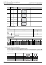
2) When using 32-bit counters (including 32-bit high speed counters)
Be sure to execute the 32-bit operation (such as LDD=, LDD> and LDD<) when comparing 32-bit
counters.
If a 32-bit counter is specified in the 16-bit operation (such as LD=, LD> and LD<), a program error or
operation error will occur.
3) Some restrictions to applicable devices
S1: The FX
3G, FX3GC, FX3U and FX3UC PLCs only are applicable.
S2: The FX
3U and FX3UC PLCs only are applicable.
4) The Load compare instruction is not available in ST.
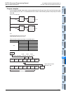
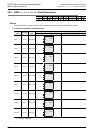
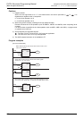
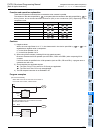
Program examples
Y10
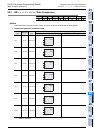
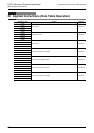
X001
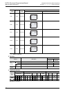
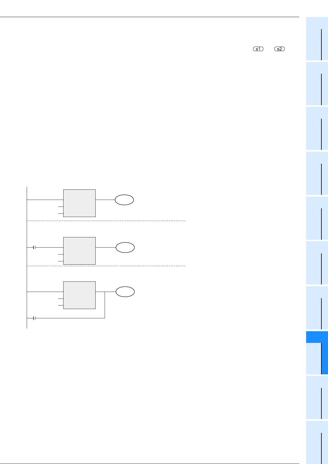
M50
M3
When the current value of the counter C10 is "200", Y010 is driven.
When the contents of D200 are "-29" or more and X001 is
ON, Y011 is set.
When the contents of the counter C200 are less than "K678,493"
or when M3 turns ON, M50 is driven.
LD=
EN
s1
s2
ENO
LD>
EN
s1
s2
ENO
LDD>
EN
s1
s2
ENO
K200
C10
[Structured ladder/FBD]
D200
K-30
Y11
C200
K678493