


11 Applied Instructions (Data Operation)
11.7 ANS / Timed Annunciator Set
245
FXCPU Structured Programming Manual
[Basic & Applied Instruction]
11
Applied Instructions
(Data Operation)
12
Applied Instructions
(High Speed
Processing)
13
Applied Instructions
(Handy
Instruction)
14
Applied Instructions
(External FX I/O
Device)
15
Applied Instructions
(External Device
(optional device))
16
Applied Instructions
(External Device)
17
Applied Instructions
(Data Transfer 2)
18
Applied Instructions
(Floating Point)
19
Applied Instructions
(Data Operation 2)
20
Applied Instructions
(Positioning
Control)
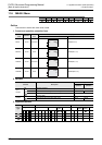
Related device
Cautions
Some restrictions to applicable devices
S1:T0 to T199
S2:S900 to 999
S3:The FX
3G, FX3GC, FX3U and FX3UC PLCs only are applicable.
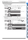
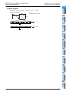
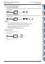
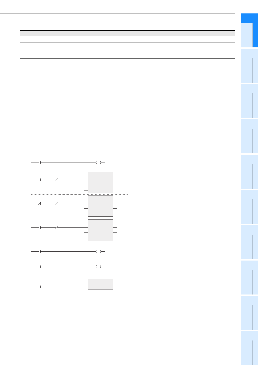
Program examples
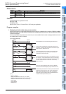
1. Displaying a fault number using an annunciator
When the program for external fault diagnosis shown below is created and the content of D8049 (smallest
state relay number in the ON status) is monitored, the smallest state relay number in the ON status from S900
to S999 is displayed.
If two or more faults are present at the same time, the next smallest fault number is displayed after the fault of
the smallest fault number is cleared.
Device Name Description
M8049 Enable annunciator When M8049 is set to ON, M8048 and D8049 are valid.
M8048 Annunciator ON When M8049 is ON and one of the state relays S900 to S999 is ON, M8048 turns ON.
D8049
Smallest state relay
number in ON status
Among S900 to S999, the smallest state relay number in the ON status is stored.
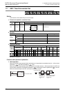
M8000
RUN monitor
Y005
Forward
end
X000
X001
Upper
limit
X002
Lower
limit
X003
Continuous
X004
Cycle
X005
Forward movement
Forward
movement
M8048
Annunciator ON
Fault display
X007
Reset
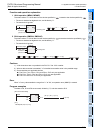
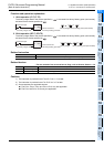
When M8049 turns ON, monitoring becomes valid.
If the forward end detection input X000 does not turn
ON within 1 second after the forward movement output
Y005 is driven, S900 turns ON.
If both the upper limit input X001 and the lower limit
input X002 are OFF for 2 seconds or more due to
a DOG error, S901 turns ON.
The switch X004 is set to ON in one operation cycle of
the machine. If the switch X004 is not set to ON while
the continuous operation mode input X003 is ON in the
machine whose tact time is less than 10 seconds,
S902 turns ON.
When one among S900 to S999 turns ON, M8048
turns ON and the fault display output Y006 turns ON.
A state relay which was set to ON by the external fault
diagnosis program is set to OFF by the reset button
X007. Every time X007 is set to ON, an operation
state relay in the ON status with the smallest device
number is reset (set to OFF) in turn.
M8049
Y005
Y006
T0
S900
K10
ANS
EN
s
m
ENO
d
T1
S901
K20
ANS
EN
s
m
ENO
d
T2
S902
K100
ANS
EN
s
m
ENO
d
ANRP
EN ENO
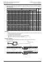
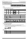
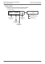
[Structured ladder/FBD]
[ ST ]
M8049:= M8000;
ANS(Y005 AND NOT X000, T0, K10, S900);
ANS(NOT X001 AND NOT X002,T1, K20, S901);
ANS(X003 AND NOT X004, T2, K100, S902);
Y005:=X005;
Y006:=M8048;
ANRP(X007);