5 Basic Instruction
5.2 LDP, LDF, ANDP, ANDF, ORP, ORF
58
FXCPU Structured Programming Manual
[Basic & Applied Instruction]
3. Applicable devices
S: Refer to "Cautions".
Function and operation explanation
1. LDP, ANDP, ORP (Initial logical operation of rising edge pulse, serial connection and parallel
connection)
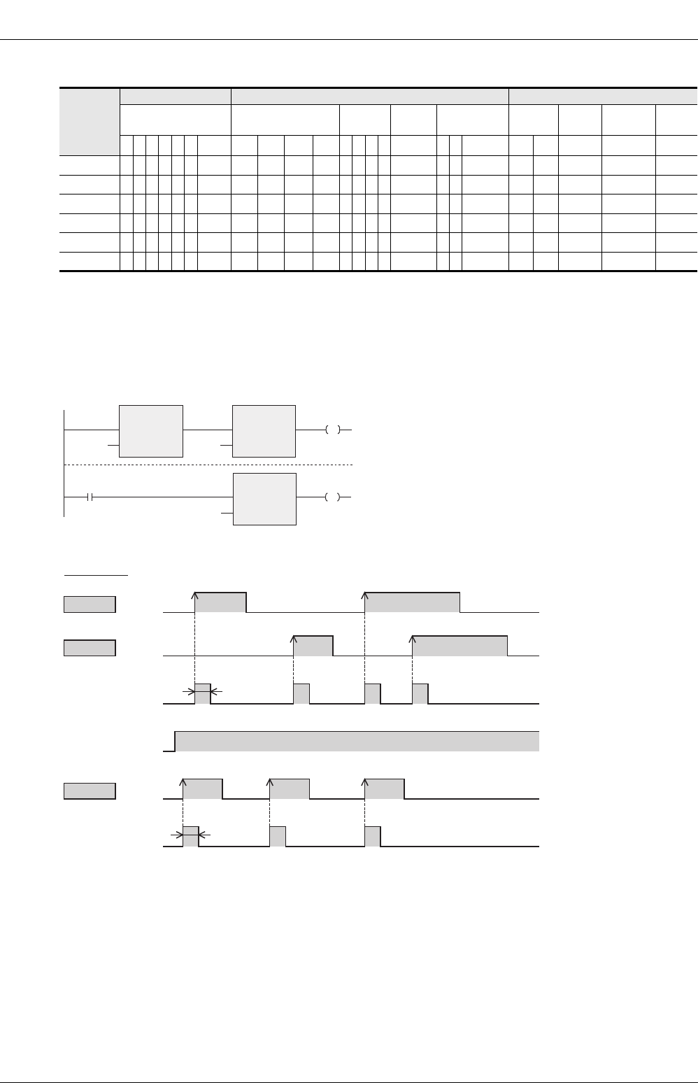
In the example shown above, M0 or M1 is ON during only one operation cycle when X000 to X002 turn ON
from OFF.
Instruction
Bit Devices Word Devices Others
System User Digit Specification
System
User
Special
Unit
Index
Constant
Real
Number
Character
String
Pointer
XYMTCS
D.b
KnX KnY KnM KnS T C D R
U\G
VZModifier K H E
""
P
LDP
zzzzzz
S1
LDF
zzzzzz
S1
ANDP
zzzzzz
S1
ANDF
zzzzzz
S1
ORP
zzzzzz
S1
ORF
zzzzzz
S1
ON
ON ON
ON
timing chart
ORP
LDP
X000
M0
X001
ON
ON during
one operation
cycle
M8000
ANDP
M1
X002
ON ON ON
ON during
one
operation
cycle
M0:=ORP(LDP(TRUE,X000),X001);
M1:= ANDP(M8000,X002);
[Structured ladder/FBD] [ ST ]
M8000
ANDP
EN
s
ENO
X002
M1
X000
LDP
EN
s
ENO
M0
ORP
EN
s
ENO
X001
RUN monitor


