


12 Applied Instructions (High Speed Processing)
298
FXCPU Structured Programming Manual
[Basic & Applied Instruction]
12.8 PLSY / Pulse Y Output
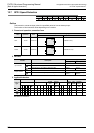
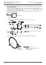
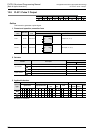
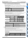
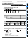
2. Monitoring the current number of generated pulses
The number of pulses output from Y000 or Y001 is stored in the following special data resistors.
*1. The FX
0S, FX0, FX0N, FXU or FX2C PLC is not compatible with this function.
*2. The FX
0S, FX0 or FX0N PLC is not compatible with this function.
The FX
U PLC of V3.07 or later is compatible.
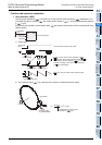
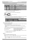
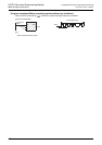
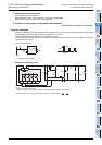
The contents of each data register can be cleared using the following program.
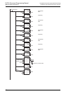
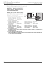
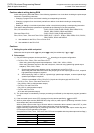
3. How to stop the pulse output
• When the command input is set to OFF, the pulse generation is immediately stopped. When the command
input is set to ON again, pulse generation operation restarts from the beginning.
• When the special auxiliary relays (M) shown below are set to ON, the pulse output is stopped.
To restart pulse output, set the device corresponding to the output signal to OFF, and then drive the pulse
output instruction again.
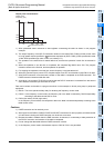
Cautions about writing during RUN
Avoid writing during RUN after either of the following operations in a circuit block including the pulse output
instruction or positioning instruction.
• Changing a program for a circuit block including a corresponding instruction.
• Changing a program for a circuit block just before or after a circuit block including a corresponding
instruction.
• Deleting or adding a circuit block just before or after a circuit block including a corresponding instruction.
This caution about the above operations is applicable to the following PLCs and instructions.
FX
1S, FX1N and FX1NC PLCs : PLSY, DPLSY, PWM, PLSR, DPLSR, ZRN, DZRN, PLSV,
DPLSV, DRVI, DDRVI, DRVA and DDRVA
FX
2N and FX2NC PLCs : PLSY, DPLSY, PWM, PLSR and DPLSR
FX
3S, FX3G, FX3GC, FX3U and FX3UC PLCs: DSZR, DVIT
*1
, DDVIT
*1
, DTBL
*2
, ZRN, DZRN, PLSV, DPLSV,
DRVI, DDRVI, DRVA and DDRVA
*1. Not available for the FX
3S, FX3G or FX3GC PLC.
*2. Not available for the FX
3S PLC.
Cautions
1. When a word device is specified as or
When the value of the word device is changed while the instruction is executed, the following operation
results.
• When the data in is changed, the output frequency changes accordingly.
• When the data in is changed, the change (new value) becomes valid the next time the instruction is
driven.
Device
Description Contents of data
High order Low order
D8141
*1
D8140
*1
Accumulated number of pulses
output from Y000
Accumulated number of pulses output from Y000 by PLSY and PLSR
instructions
D8143
*1
D8142
*1
Accumulated number of pulses
output from Y001
Accumulated number of pulses output from Y001 by PLSY and PLSR
instructions
D8137
*2
D8136
*2
Total accumulated number of
pulses output from Y000 and Y001
Total accumulated number of pulses output from Y000 and Y001 by
PLSY and PLSR instructions.
Device
Description
FX3U, FX3UC FX3S, FX3G, FX3GC FX1S, FX1N, FX1NC
M8349 M8145, M8349 M8145 Immediately stops pulse output from Y000.
M8359 M8146, M8359 M8146 Immediately stops pulse output from Y001.
Command
input
DMOV
EN
s
ENO
d
K0 Low order devices in the table above