


13 Applied Instructions (Handy Instruction)
13.1 IST / Initial State
313
FXCPU Structured Programming Manual
[Basic & Applied Instruction]
11
Applied Instructions
(Data Operation)
12
Applied Instructions
(High Speed
Processing)
13
Applied Instructions
(Handy
Instruction)
14
Applied Instructions
(External FX I/O
Device)
15
Applied Instructions
(External Device
(optional device))
16
Applied Instructions
(External Device)
17
Applied Instructions
(Data Transfer 2)
18
Applied Instructions
(Floating Point)
19
Applied Instructions
(Data Operation 2)
20
Applied Instructions
(Positioning
Control)
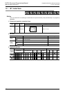
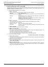
Function and operation explanation
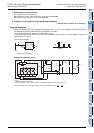
• In , designate beginning input of operation mode.
Selection switch for operation mode occupies 8 points from the head device designated in , and the
following switch functions are assigned individually.
As shown in the table below, when X020 is assigned, X020 to X024 must be set in rotary switch so as not
to be turned ON simultaneously.
Wiring is not needed for switches not in use, but such switches cannot be used in other applications
because they are occupied by IST command.
• In , designate minimum number of practical state (for automatic mode).
• In , designate maximum number of practical state (for automatic mode).
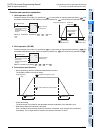
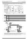
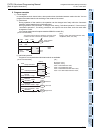
1. Control of device by switch operation (occupied device)
When command input is turned ON, next device is automatically changed over and controlled. No change if
command input is turned OFF.
*1. Cleared when changed from RUN to STOP
*2. Process during END command execution
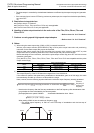
The following states should not be programmed as general states.
If return home end (M8043) is not ON, all outputs are OFF if changed over to individual (X020), return to
home position (X021), or automatic (X022, X023, X024).
Automatic operation can be resumed after returning to home position completely.
→ Before introduction, refer to "IST command introduction examples (examples of work transfer
mechanism)" given below.
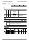
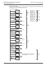
Source
Device No.
(example)
Switch function Source
Device No.
(example)
Switch function
X020 Individual operation
+4
X024 Continuous operation
+1
X021 Return to home position
+5
X025 Return home start
+2
X022 Stepping
+6
X026 Automatic start
+3
X023 One-cycle operation
+7
X027 Stop
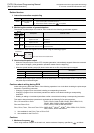
Device No. Operation function Device No. Operation function
M8040 Transfer ban S0 Initial state of individual operation
M8041
*1
Transfer start S1 Initial state of return to home position
M8042 Start pulse S2 Initial state of automatic operation
M8043
*1
Return home end
M8045 All output reset ban
M8047
*2
STL monitor valid
Device No. Operation function
S0 to S9
Occupied for initial state.
• S0 to S2 can be used for individual operation, return to home position, or automatic operation as specified
above.
• S3 to S9 can be used freely.
S10 to S19 Occupied for return to home position.
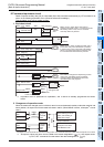
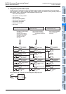
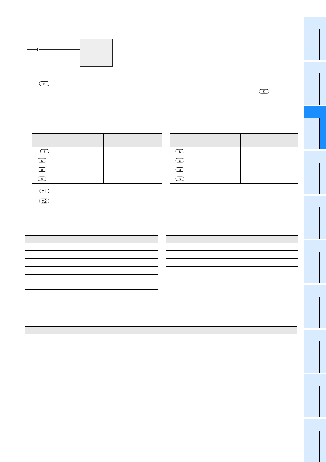
Command input
IST
EN
s
ENO
d1
d2
Minimum state
Maximum state
Head bit device
number of the
selector switch
in the operation mode