16 Applied Instructions (External Device)
16.5 RMWR / Write to F2-32RM
426
FXCPU Structured Programming Manual
[Basic & Applied Instruction]
Function and operation explanation
• This instruction sends output prohibit information from the PLC to the
F
2-32RM type programmable cam switch.
• The content of the device specified by , is determined by the
connection position of FX
2-24EI type special adapter.
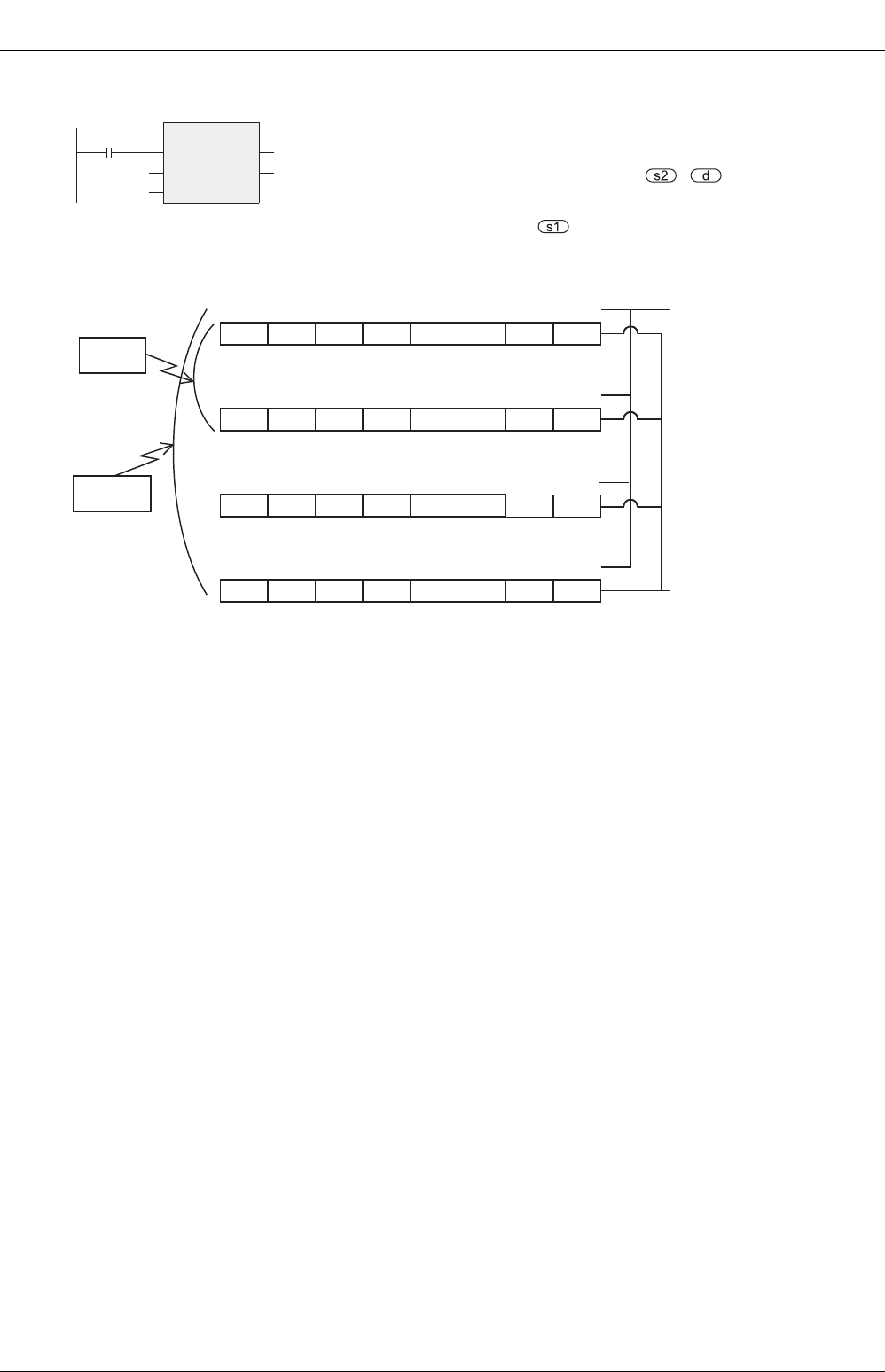
• The device specified by is an output prohibit table, and is handled
as octagonal number as shown in the example below.
X000
Writing of output prohibit information
Y030M500
RMWR
EN
s1
s2
ENO
d
X040
M507 M506 M505 M504 M503 M502 M501 M500
Y007 Y006 Y005 Y004 Y003 Y002 Y001 Y000
M517 M516 M515 M514 M513 M512
M511 M510
Y017 Y016 Y015 Y014 Y013 Y012
Y011 Y010
M527 M526 M525 M524 M523 M522
M521 M520
Y027 Y026 Y025 Y024 Y023 Y022
Y021 Y020
M537 M536 M535 M534 M533 M532 M531 M530
Y037 Y036 Y035 Y034 Y033 Y032 Y031 Y030
RMWR
RMWRP
DRMWR
DRMWRP
Output number of
F
2-32RM
For example, when
M500 is turned ON,
Y000 is output
prohibited, and
cannot be turned ON.
Auxiliary relay numbe
r
of FXU, FX2C


