


5 Basic Instruction
5.5 Operating Counters
70
FXCPU Structured Programming Manual
[Basic & Applied Instruction]
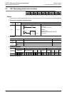
2. Counter reset
After completing to count, the count value and contact condition does not change until the RST instruction is
executed.
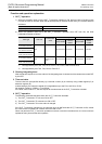
3. Counter set value
The set value of the counter can be specified directly by a decimal number (K) or indirectly using a data
register (D) or extension register (R).
Indirect setting by the extension register (R) is applicable only to the FX
3U and FX3UC PLCs.
No negative numbers (-32768 to -1) can be set.
If set to "0", the same process as 1 takes place.
4. When using counter device
When a counter device is specified in a program, use the following depending on the locations of use.
• Used as contacts: CS
• Used as a coil: CC
• Used as a current value: CN
Cautions
1) Some restrictions to applicable devices
S1: The FX
3G, FX3GC, FX3U and FX3UC PLCs only are applicable.
S2: Only the FX
3U and FX3UC PLCs can index the target device.
A 32-bit counter cannot be indexed.
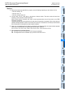
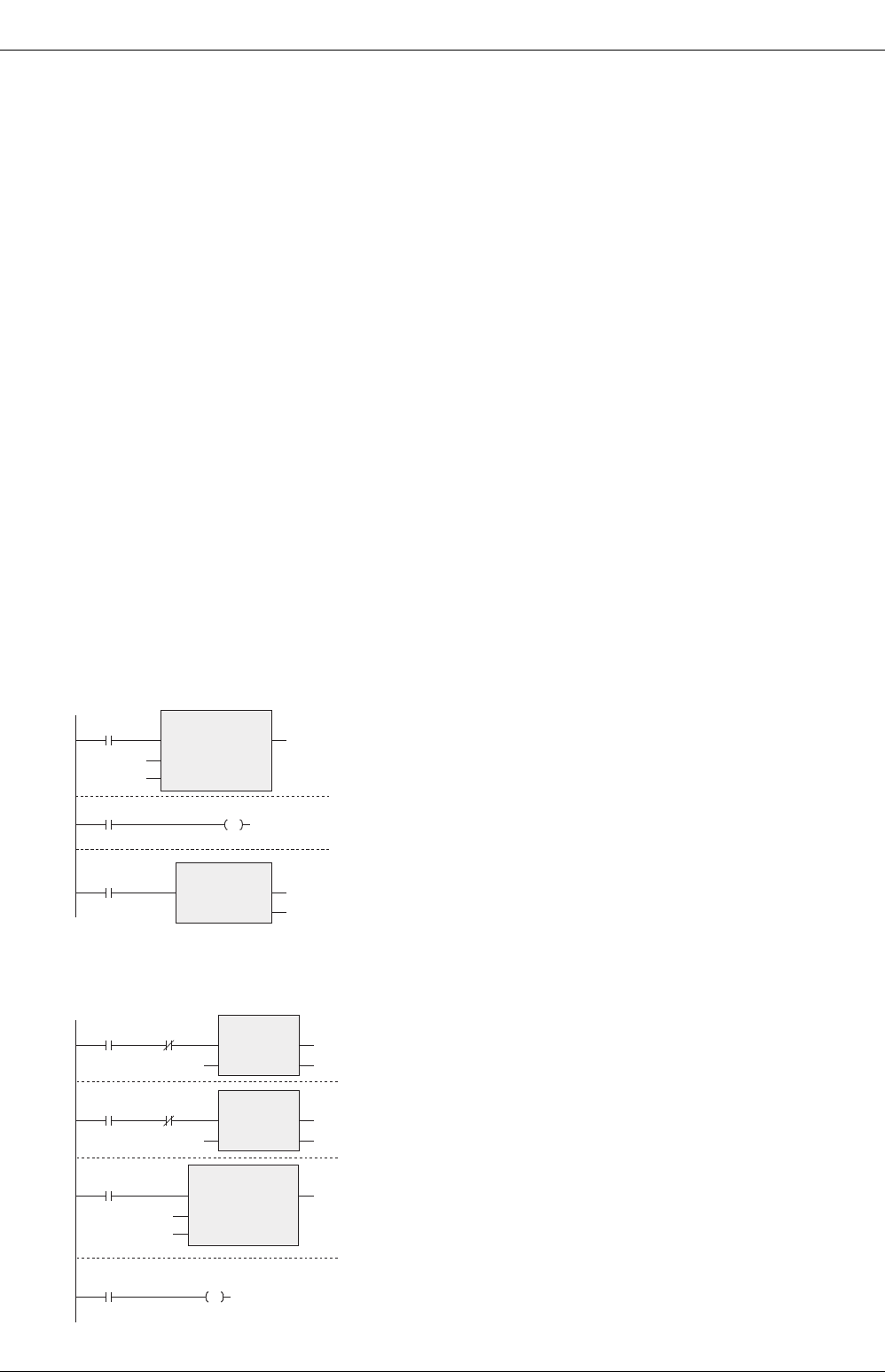
Program example
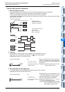
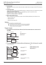
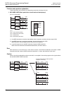
1. This program turns ON Y30 when X0 turns ON 10 times and resets the counter when X1
turns ON.
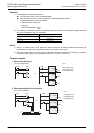
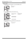
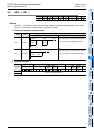
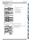
2. This program sets "10" to C10 when X0 turns ON and sets to "20" to C10 when X1 turns ON.
OUT_C
EN ENO
CC10
X000
CCoil
CValue
K10
CS10 Y030
RST
EN ENO
d
CN10
X001
[Structured ladder/FBD]
OUT_C(X0,CC10,10);
OUT(CS10,Y30);
RST(X1,CN10);
[ ST ]
CS10 Y030
OUT_C
EN ENO
CC10
X003
CCoil
CValue
D0
MOVP
EN
s
ENO
d
D0
X000 X001
10
MOVP
EN
s
ENO
d
D0
X001 X000
20
Sets "10" to D0 when
X0 turns ON.
Sets "20" to D0 when
X1 turns ON.
C10 counts with the
data stored in D0 as
the set value.
When C10 completes counting,
Y30 turns ON.
[Structured ladder/FBD]
MOVP(X0 AND NOT X1,10,D0);
MOVP(X1 AND NOT X0,20,D0);
OUT_C(X3,CC10,D0);
OUT(CS10,Y30);
[ ST ]