


14 Applied Instructions (External FX I/O Device)
14.5 SEGL / Seven Segment With Latch
370
FXCPU Structured Programming Manual
[Basic & Applied Instruction]
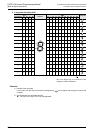
14.5.1 Selection procedure of 7-segment display unit
You can select the 7-segment display unit depending on the electrical content by referring to the example
below.
→ As for the actual wiring, see the hardware manual of the PLC main body.
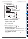
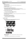
1. Check points by 7-segment specification
1) Check if the data input, and input voltage and current characteristics of strobe signal are satisfying the
output specification of the PLC or not.
- Check if the input signal voltage (Lo) is about 1.5 V or less.
- Check if the input voltage is DC 5 V to DC 30 V.
2) Check if the BCD decoding or latching function is provided or not.
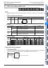
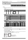
14.5.2 Selection procedure of parameter n by specification of 7-segment display
The value to be set in parameter n varies with the signal logic of 7-segment display.
Select in the following procedure.
A check column is provided in the final line of the table. Check the corresponding positive or negative logic,
and select the parameter accordingly.
1. Role of parameter n
Parameter n is a number selected depending on the logic (positive or negative) of 7-segment data input, the
logic (positive or negative) of strobe signal, or control of 4 digits and 1 set or control of 2 sets.
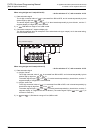
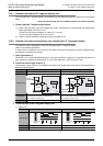
2. Check the output logic of the PLC
The transistor output of the PLC is available in two types, sync output and source output. The specification is
different as shown below.
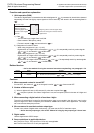
3. Check the logic of the 7-segment display unit.
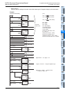
1) Data input
Logic Negative logic Positive logic
Output format Sync output [- common] Source output [+ common]
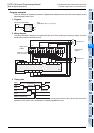
Output circuit
Explanation
Because of transistor output (sync), when the internal logic
is 1 (ON output), the output is LOW level (0V).
This is called the negative logic.
Because of transistor output (source), when the internal
logic is 1 (ON output), the output is HIGH level (V+).
This is called the positive logic.
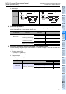
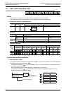
Logic check
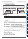
Logic Negative logic Positive logic
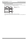
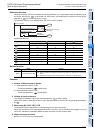
Timing chart
Explanation Becoming BCD data at LOW level Becoming BCD data at HIGH level
Logic check
ON
PLC
LOW
Logic 1
Pull-up
resistance
COM1
Y000
ON
PLC
Logic 1
Pull-down
resistance
V+
HIGH
+V0
Y000
7-segment
display
2
1
4
8
H
H
HH
H
L
L
L
+1
+2
+3
d
d
d
d
+1
+2
+3
7-segment
display
2
1
4
8
HH
H
d
d
d
d