14 Applied Instructions (External FX I/O Device)
14.1 TKY / Ten Key Input
356
FXCPU Structured Programming Manual
[Basic & Applied Instruction]
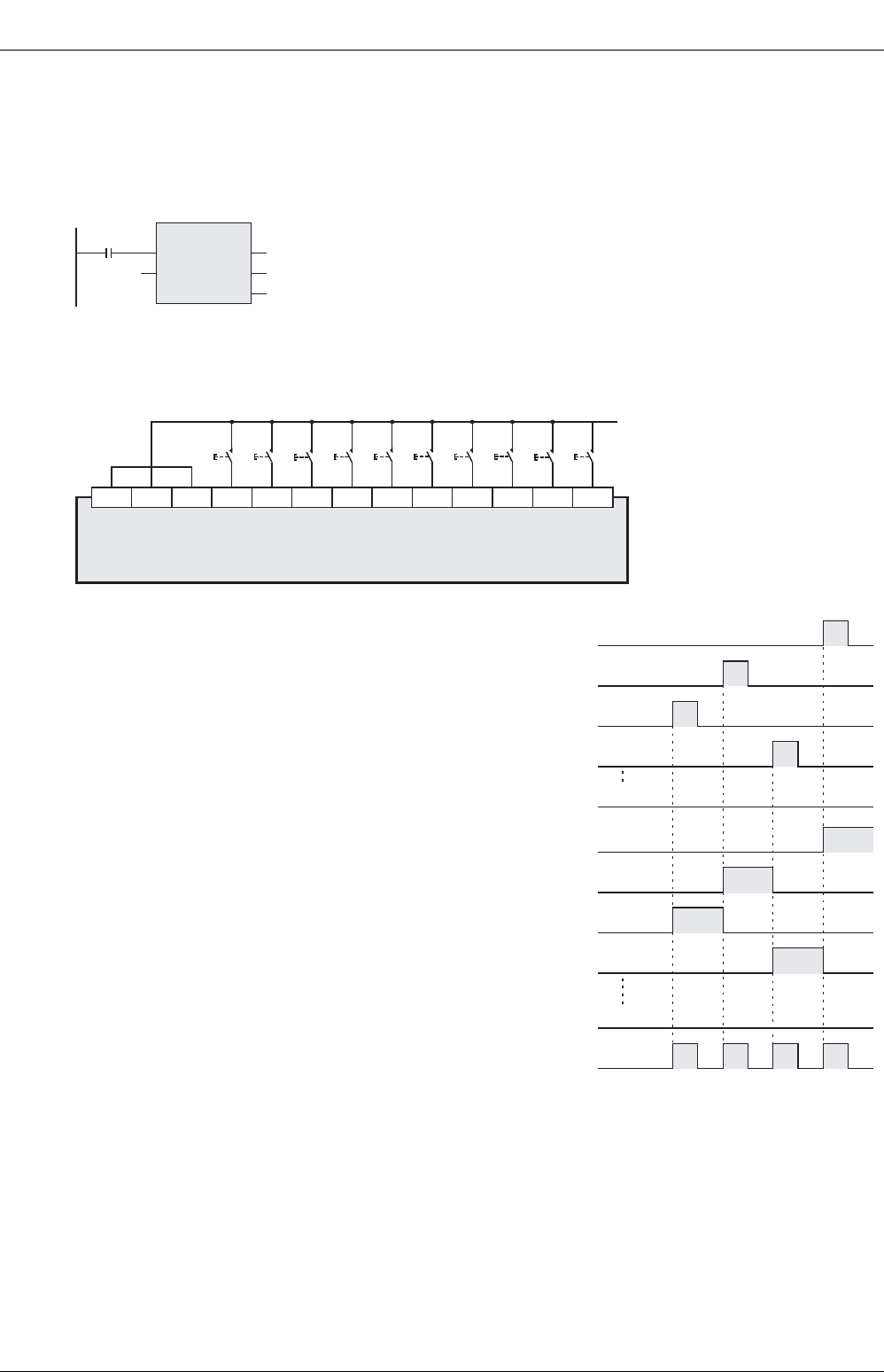
Program examples
This is an explanation of an example in which the input X000 is the beginning, and numeric keys 0 to 9 are
connected.
1. Program
2. Wiring diagram
This wiring diagram is an example of FX3U PLC (sync input). As for the actual wiring connection, see the
manual of the PLC.
3. Timing chart
1) When numeric keys are pressed in the sequence of 1, 2, 3, 4,
the content of D0 is 2,130.
Numerical value more than 9,999 overflows sequentially from
the upper digits. (The actual content of D0 is BIN data.)
2) When X002 is pressed, M12 is set (ON) until other key is
pressed. It is the same when other key is pressed.
Thus, depending on the operation of input X000 to X011,
operation of M10 to M19 is carried out.
3) When any key is pressed, the key sense output M20 is kept ON
while being pressed.
X030
TKY
EN
s
ENO
d1
d2
X000 D0
M10
[Structured ladder/FBD] [ST]
TKY(X030, X000, D0, M10);
PLC
S/S X000 X001 X002 X003 X005X004 X006 X007
56781234
X010 X011
0 9Numeric key
24V 0V
X000
X001
X002
X003
1
2
3
4
M 10
M 11
M 12
M 13
M 20
1234
Key sense output
X011
M 19


