


12 Applied Instructions (High Speed Processing)
265
FXCPU Structured Programming Manual
[Basic & Applied Instruction]
11
Applied Instructions
(Data Operation)
12
Applied Instructions
(High Speed
Processing)
13
Applied Instructions
(Handy
Instruction)
14
Applied Instructions
(External FX I/O
Device)
15
Applied Instructions
(External Device
(optional device))
16
Applied Instructions
(External Device)
17
Applied Instructions
(Data Transfer 2)
18
Applied Instructions
(Floating Point)
19
Applied Instructions
(Data Operation 2)
20
Applied Instructions
(Positioning
Control)
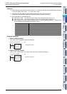
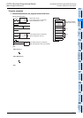
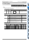
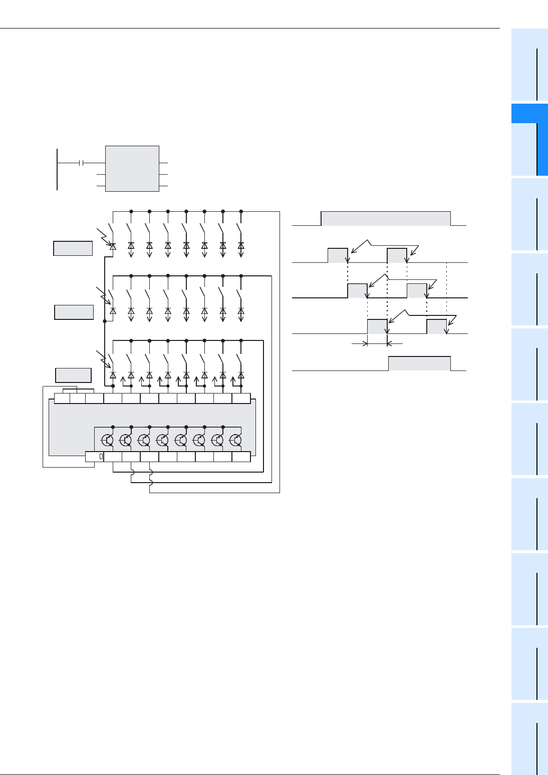
12.3 MTR / Input Matrix
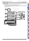
Program examples
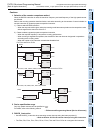
n = Three outputs (Y020, Y021 and Y022) are set to ON in turn repeatedly.
Every time an output is set to ON, eight inputs in the 1st, 2nd and 3rd columns are received in turn repeatedly,
and stored to M30 to M37, M40 to M47, and M50 to M57 respectively.
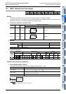
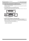
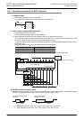
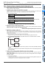
In this program example, the FX
3U series main unit (sink input / sink output) is used. For the wiring, refer to
the manual of the PLC used.
M0
Y020
1) 4)
Y021
2) 5)
3) 6)
Y022
M8029
(Execution complete)
20ms
X021
M 51
X022
M 52
X023
M 53
X024
M 54
X025
M 55
X026
M 56
X027
M 57
M 50M 40
X020 X021 X022 X023 X024 X025 X026 X027
X021
X022
X023 X024 X025 X026 X027
M 41
M 42
M 43
M 44
M 45
M 46
M 47
M 31
M 32
M 33
M 34
M 35
M 36
M 37
M 30
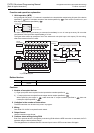
S/S0V24V
COM
Y020 Y021 Y022 Y023 Y024 Y025 Y026 Y027
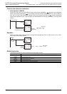
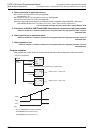
M0
MTR
EN
s
n
ENO
d1
d2
X020
K 3
Y020
M30
[Structured ladder/FBD] [ST]
MTR(M0,X020,K3,Y020,M30);
Diode
0.1A(50V)
Diode
0.1A(50V)
Diode
0.1A(50V)
1st column input is received.
2nd column input is received.
3rd column input is received.
2nd column
3rd column
1st column
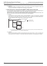
PLC
Input
Output
(Y) [Sink]
(X) [Sink]