


35 Interrupt Function and Pulse Catch Function
814
FXCPU Structured Programming Manual
[Basic & Applied Instruction]
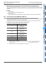
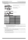
35.8 Pulse width/Pulse period measurement function [M8075 to M8083, D8074 to D8097]
2) Pulse period measurement
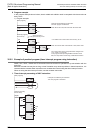
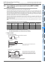
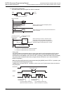
The pulse period of the input signal from X000 is measured.
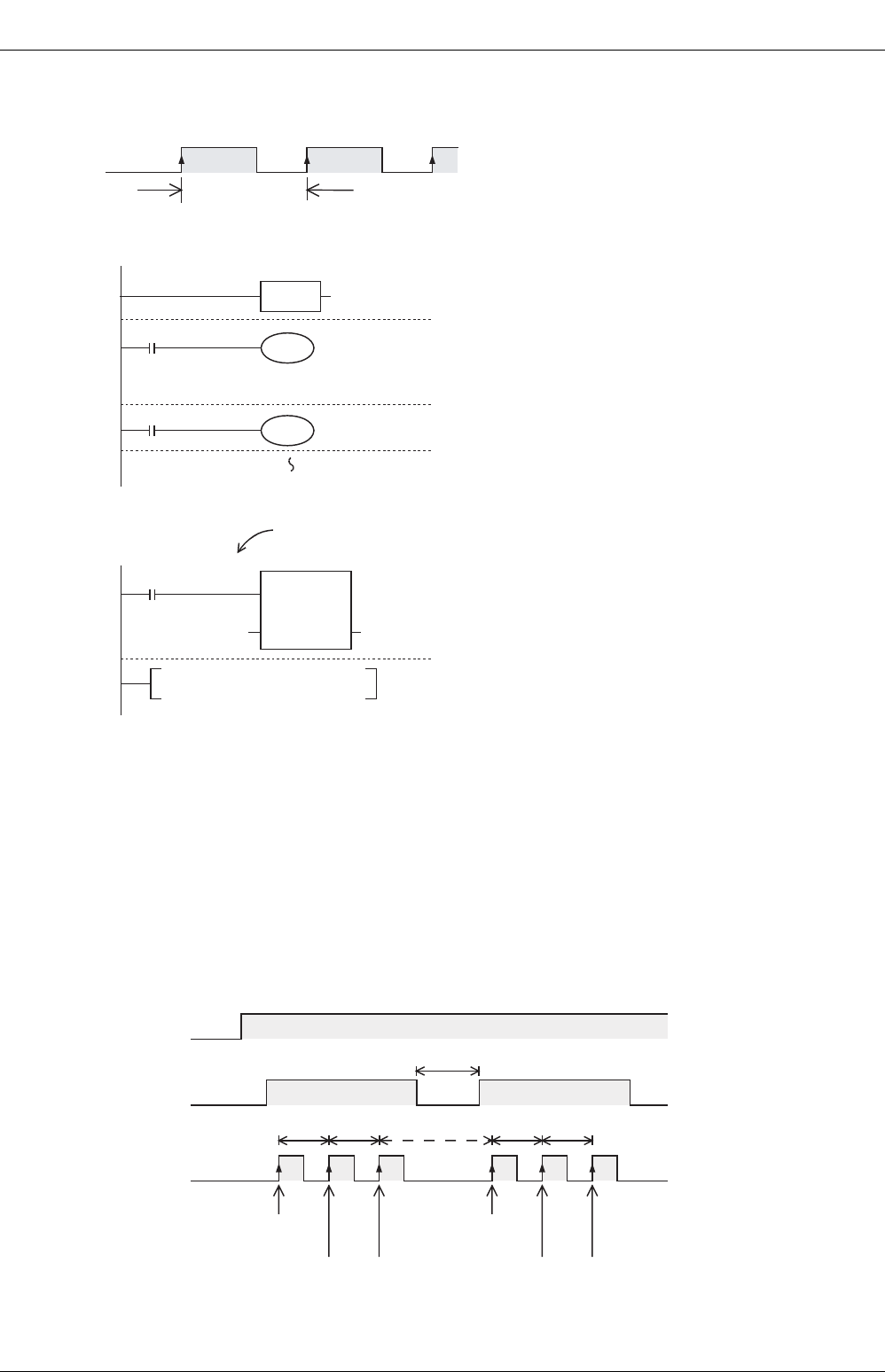
- Timing chart
The pulse period is not measured when the input signal rises for the first time after the PLC mode is
changed from STOP to RUN, or when the input signal rises for the first time after the pulse period
measurement mode (M8080) is set to ON from OFF. (Accordingly, D8078 and D8079 are not updated.)
The pulse period is measured when the input signal rises at the next time. (As a result, D8078 and
D8079 are updated.)
Make the pulse width/pulse period measurement setting flag (M8080) remain OFF for 1 operation cycle
or more when discontinuing the pulse input.
If M8080 does not remain OFF for 1 operation cycle or more, the "a" period shown below is stored as
the pulse period.
This duration is measured.
X000
OFF
ON
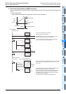
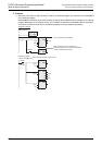
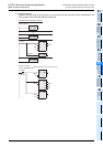
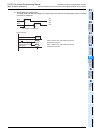
EN ENO
EI
DMOV
[Main program]
[Interrupt program]
(Event: I001)
X000 Rising edge
interrupt
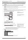
*1. VAR_01 is a global label and is defined as D8078.
*2. VAR_02 is a global label and is defined as D0.
X000 is used for the pulse width/pulse period
measurement function.
When X002 turns ON, the pulse period measurement
mode is actuated.
When the interrupt routine is executed at the
rising edge of the input signal from X000, the
pulse period of input signal from X000 stored in
D8078 and D8079 is transferred to D1 and D0.
M8075
M8000
RUN monitor
VAR_01
*1
VAR_02
*2
Pulse width/Pulse
period measurement
setting flag
M8076
EN ENO
sd
X2
M8080
User program
M8080
RUN/STOP
RUN
ON ON
X000
The pulse period is
not measured.
pulse period
The pulse period is
not measured.
The pulse period is measured.
(D8078 and D8079 are updated.)
The pulse period is measured.
(D8078 and D8079 are updated.)
one operation cycle
a