


10 Applied Instructions (Rotation and Shift Operation)
10.6 SFTL / Bit Shift Left
211
FXCPU Structured Programming Manual
[Basic & Applied Instruction]
1
Outline
2
Instruction List
3
Configuration of
Instruction
4
How to Read
Explanation of
Instructions
5
Basic Instruction
6
Step Ladder
Instructions
7
Applied Instructions
(Program Flow)
8
Applied Instructions
(Move and
Compare)
9
Applied Instructions
(Arithmetic and
Logical Operation)
10
Applied Instructions
(Rotation and
Shift Operation)
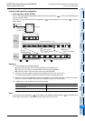
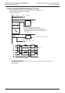
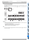
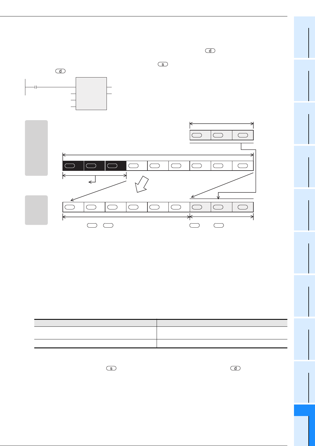
Function and operation explanation
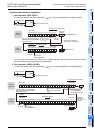
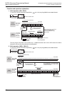
1. 16-bit operation (SFTL, SFTLP)
For "n1" bits (shift register length) starting from the bit device specified by , "n2" bits are shifted leftward
(1) and 2) shown below).
After shift, "n2" bits from the bit device specified by are transferred to "n2" bits from the bit device
specified by (3) shown below).
Cautions
1) Some restrictions to applicable devices
S1:The FX
3U and FX3UC PLCs only are applicable. Not indexed (V, Z).
S2:The FX
3S, FX3G, FX3GC, FX3U and FX3UC PLCs only are applicable.
S3:The FX
3G, FX3GC, FX3U and FX3UC PLCs only are applicable.
2) Instructions of pulse operation type are not provided in the FX
0S, FX0 or FX0N PLC.
To execute pulse operation, make the instruction execution condition pulse type.
3) Note that "n2" bits are shifted every time the command input turns ON from OFF in SFTLP instruction, but
that "n2" bits are shifted in each operation cycle in SFTL instruction.
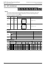
4) Limitation to n1 and n2 differs from one PLC to another.
Error
If the transfer source specified by is equivalent to the shifted device specified by , an operation error
occurs (error code: K6710). (Applicable only to the FX
3U and FX3UC PLCs)
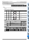
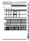
PLC Limit
FX
1N, FX1NC, FXU, FX2C, FX2N, FX2NC, FX3S, FX3G,
FX
3GC, FX3U, FX3UC
n2≤n1≤1024
FX0S, FX0, FX0N, FX1S
n2≤n1≤512
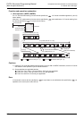
SFTL
EN
s
n1
ENO
d
n2
Command input
Stored data
Shift data
Bit data length
Number of bits
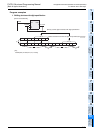
Before
execution
After
execution
n2 (in the case of "n2 = 3")
n1 (in the case of "n1 = 9")
1)
Overflow
(data to be deleted)
3) Copy
2)
"n2" bits are shifted
leftward (n2 = 3)
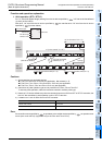
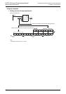
+1 +2
s ss
+8 +7 +6
d d d
+5 +4 +3
d d d
+2 +1
d d d
+2 +1 +8 +7 +6 +5 +4 +3
d d dd d d d d d
+2 to before shift (n2 = 3).
ssd
to +5 before shift (n2 = 3)
d