


9 Applied Instructions (Arithmetic and Logical Operation)
9.10 NEG / Negation
193
FXCPU Structured Programming Manual
[Basic & Applied Instruction]
1
Outline
2
Instruction List
3
Configuration of
Instruction
4
How to Read
Explanation of
Instructions
5
Basic Instruction
6
Step Ladder
Instructions
7
Applied Instructions
(Program Flow)
8
Applied Instructions
(Move and
Compare)
9
Applied Instructions
(Arithmetic and
Logical Operation)
10
Applied Instructions
(Rotation and
Shift Operation)
Function and operation explanation
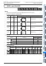
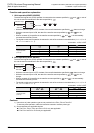
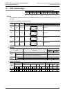
1. 16-bit operation(NEG, NEGP)
Each bit of the device specified by is inverted (0 → 1, 1 → 0), "1" is added, and then the result is stored
in the original device.
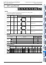
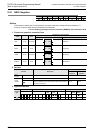
2. 32-bit operation(DNEG, DNEGP)
Each bit of the device specified by is inverted (0 → 1, 1 → 0), "1" is added, and then the result is stored
in the original device.
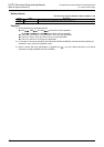
Cautions
1) Note that the complement is obtained in every scan time (operation cycle) in a continuous operation type
instruction (NEG,DNEG).
2) Some restrictions to applicable devices
S1:The FX
3U and FX3UC PLCs only are applicable.
Program examples
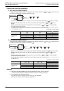
The program examples below are provided to obtain the absolute value of a negative binary value.
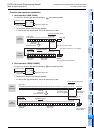
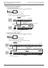
1. Obtaining the absolute value of a negative value using NEG instruction
Command input
Complement data
NEG
EN ENO
d
( ) +1 →
d d
Command input
Complement data
DNEG
EN ENO
d
( +1, )+1 = ( +1, )
d d d d
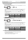
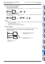
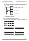
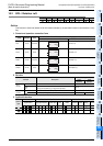
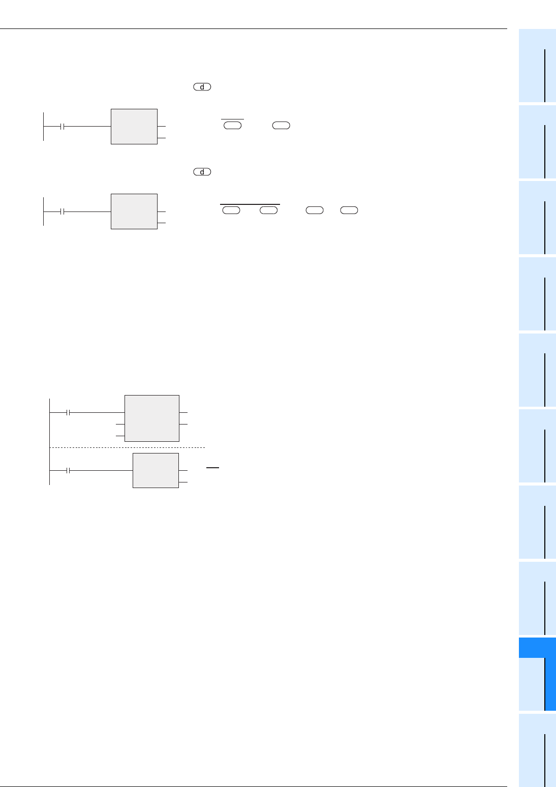
In BON (ON bit check) instruction, M0
turns ON when the bit 15 (b15 among
b0 to b15) of D10 is "1".
NEGP instruction is executed for D10
only when M0 turns ON.
M0
D10
BON
EN
s
n
ENO
d
M8000
D10
K15
M0
RUN
monitor
D10
→
D10
[Structured ladder/FBD]
[ ST ]
BON(M8000, D0, K15, M0);
NEGP(M0, D10);
NEGP
EN ENO
d