


14 Applied Instructions (External FX I/O Device)
14.8 PR / Print (ASCII Code)
379
FXCPU Structured Programming Manual
[Basic & Applied Instruction]
11
Applied Instructions
(Data Operation)
12
Applied Instructions
(High Speed
Processing)
13
Applied Instructions
(Handy
Instruction)
14
Applied Instructions
(External FX I/O
Device)
15
Applied Instructions
(External Device
(optional device))
16
Applied Instructions
(External Device)
17
Applied Instructions
(Data Transfer 2)
18
Applied Instructions
(Floating Point)
19
Applied Instructions
(Data Operation 2)
20
Applied Instructions
(Positioning
Control)
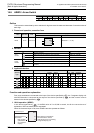
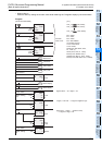
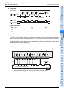
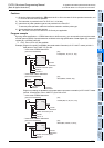
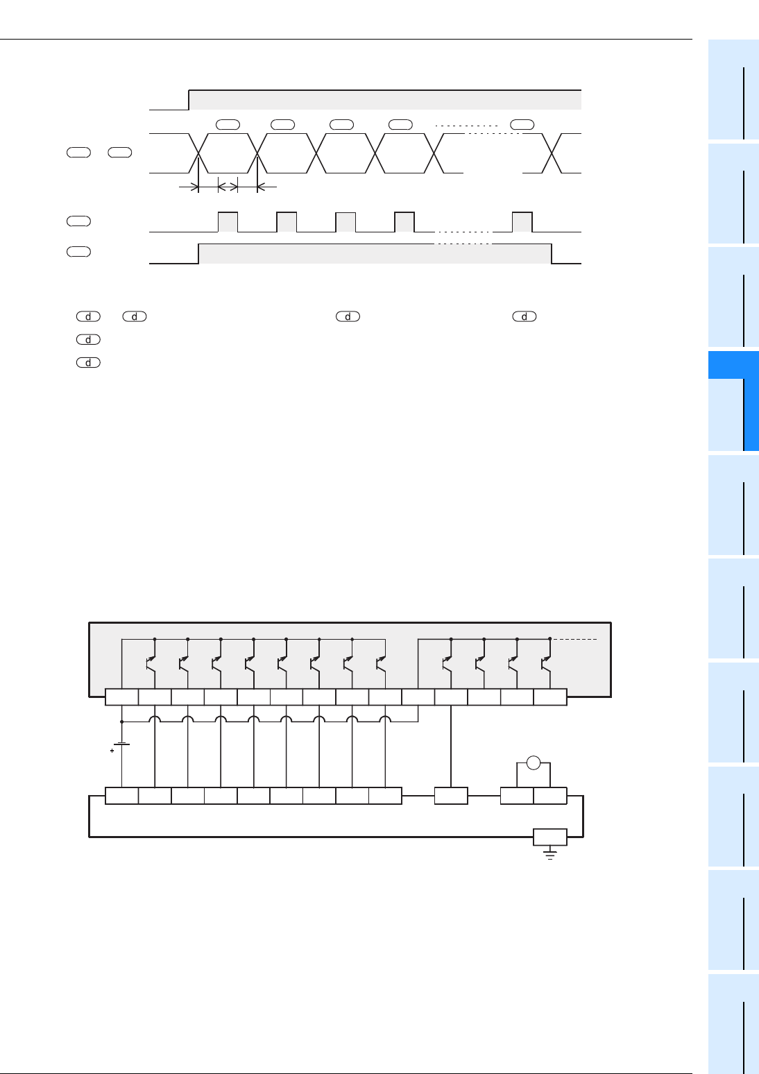
2. Timing chart
Type of output signal
• to +7 : Transmission output is the lower bit side, and +7 is the higher bit side.
• +8 : Strobe signal
• +9 : Execution busy flag Operation conforms to the timing chart above.
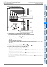
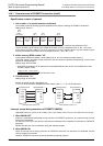
Extension function
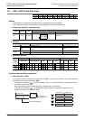
1. 16-byte serial output
By ON/OFF control of special auxiliary relay M8027, the number of characters of output varies in every two
times of instruction drive. In the case of M8027=OFF, the operation is 8-byte serial output (fixed in 8
characters), and in the case of M8027=ON, it is 16-byte serial output (1 to 16 characters).
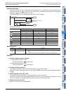
An example of display of 16 characters or less (1 character/byte) is explained by referring to a display device
(example: A6FD type external display unit
*1
).
The display data is supposed to be stored in hexadecimal code in D300 to D307.
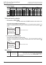
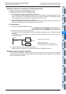
1) A6FD type external display unit
*1
connection example
The PLC shown below is an example of FX
2N-16EYT (sink output) connected to FX3U-32M.
*1. A6FD type external display unit is out of production since November 2002.
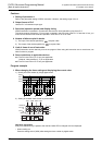
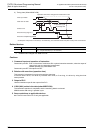
T0
T0
T0
T0: Scan time (ms)
ABCD H
Command input
+8 Strobe
+9 Execution busy flag
+1 +2 +3 +7
d
to +7 Data
d d
d
s1s1s1s1s1
AC100/200V
LG
Y031 Y032
24V
D 0 D 1 D 2 D 3 D 4 D 5 D 6 D 7
Y033
COM1
Y020 Y021 Y022 Y023 Y024 Y025 Y026 Y027
COM2
Y030
STR
A6FD type external display unit
*1
COM
12V
AC AC
NC
~
PLC