


12 Applied Instructions (High Speed Processing)
272
FXCPU Structured Programming Manual
[Basic & Applied Instruction]
12.4 DHSCS, DHSCS_I / High Speed Counter Set, High Speed Interrupt Counter Set
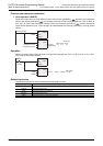
2) Operation
Even if the condition for setting the output to ON or OFF is given as the comparison result, the
comparison result does not change when an instruction is simply driven.
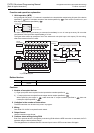
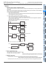
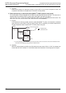
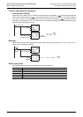
5. Reset operation by an external terminal [M8025
*1
: DHSC (external reset) mode]
For a high speed counter equipped with an external reset terminal (R) such as C241, an instruction is
executed and the comparison result is output at the rising edge of the reset input signal.
(The FX
U PLC of V2.1 or later and produced February 1990 or later are compatible with this function. The
FX
0S, FX0, FX0N, FX1S, FX1N, FX1NC, FX3S, FX3G or FX3GC is not compatible.)
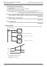
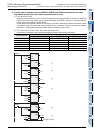
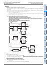
1) Program
If an instruction for the high speed counter is used while M8025
*1
is driven, the instruction is executed
again when the current value of the high speed counter C241 is cleared by an external reset terminal.
And the comparison result is output even if a counting input is not given.
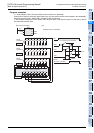
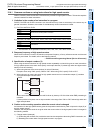
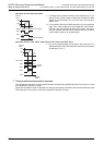
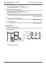
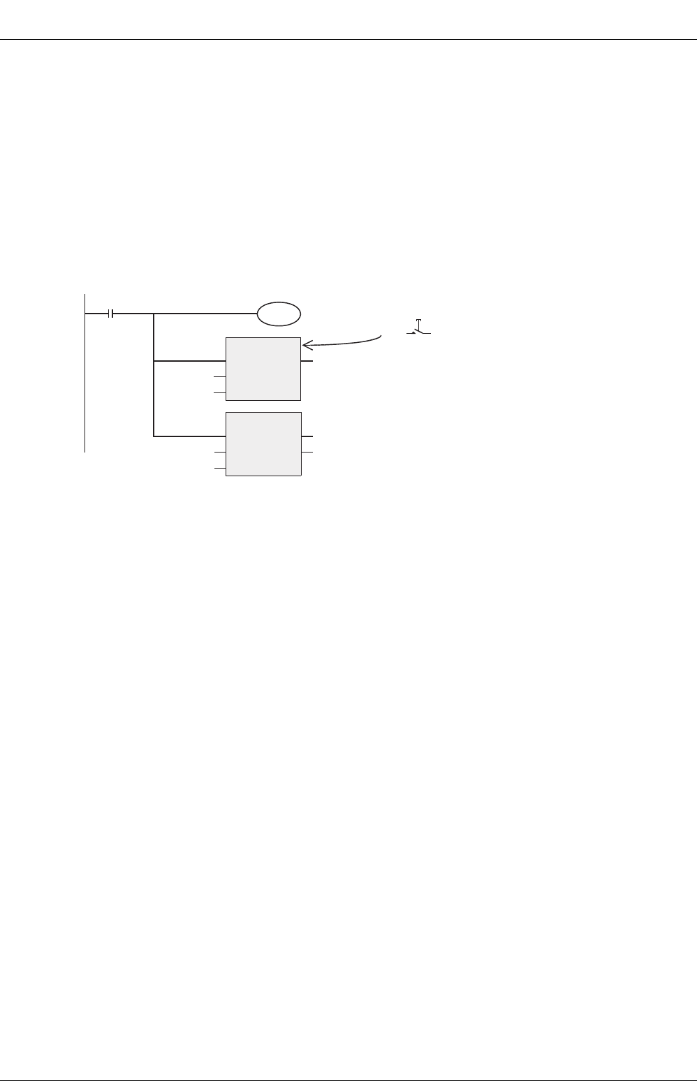
2) Operation
When the external reset input X001 turns ON while the current value of C241 is "100", for example, the
current value of C241 is reset to "0". And Y000 is reset at this time even if a counting input is not given.
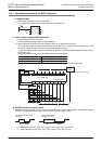
M8000
RUN
monitor
M8025
External reset mode
*1
DHSCR
EN
s1
s2
ENO
d
CN241
Y000
K0
External reset
terminal for C241
X001
OUT_C_32
EN
CCoil
CValue
ENO
CC241
K9999
*1. It is not necessary to drive M8025 for the FX
0S
, FX
0
, FX
0N
, FX
1S
, FX
1N
, FX
1NC
, FX
3S
, FX
3G
and FX
3GC
PLCs.
The above reset operation takes place as a basic function.