


35 Interrupt Function and Pulse Catch Function
799
FXCPU Structured Programming Manual
[Basic & Applied Instruction]
31
Applied Instructions
(Data Transfer 3)
32
Applied Instructions
(High Speed
Processing 2)
33
Applied Instructions
(Extension File
Register Control)
34
Applied Instructions
(FX
3U
-CF-ADP)
35
Interrupt Function
and Pulse Catch
Function
A
Relationships
between devices
and addresses
B
Applied
Instruction List
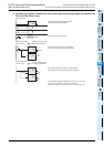
35.3 Input Interrupt (Interrupt Triggered by External Signal) [Without Delay Function]
5. How to disable each interrupt input
When either one among M8050 to M8055 is set to ON in a program, interrupts from the corresponding input
number are disabled.
(Refer to the previous page for the correspondence.)
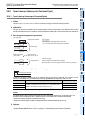
6. Cautions
1) Do not use an input two or more times.
Make sure that an input relay number used as an interrupt pointer is not used in high speed counters,
pulse catch functions and pulse density instructions which use the same input range.
2) Automatic adjustment of the input filter
When an input interrupt pointer I
0 is specified, the input filter of the input relay is automatically
changed to the input filter for high speed receiving.
Accordingly, it is not necessary to change the filter value using REFF instruction or special data register
D8020 (input filter adjustment).
The input filter of an input relay not being used as an input interrupt pointer operates at 10 ms (initial
value).
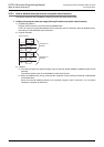
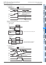
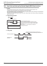
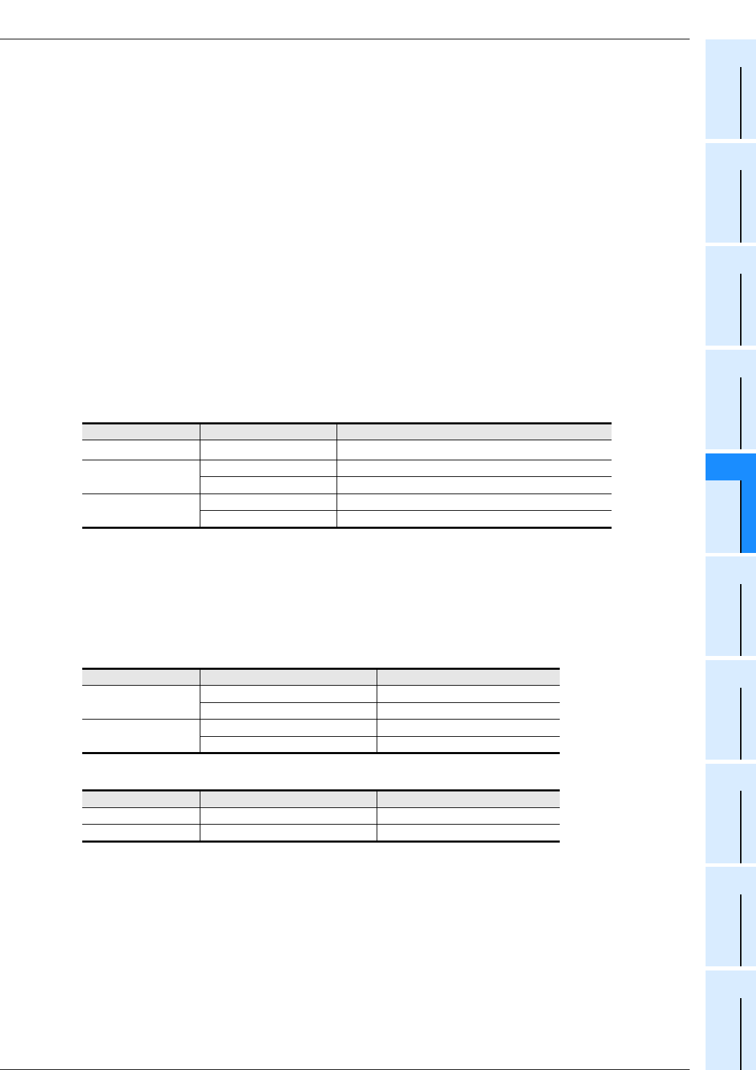
3) Pulse width of input interrupt
For executing input interrupt by an external signal, it is necessary to input the ON or OFF signal having
the duration shown in the table below or more.
For the FX
3S, FX3G, FX3GC, FX3U and FX3UC PLCs
*1. When using the input filter at the filter value of 5 μs or when receiving a pulse whose response
frequency is 50 k to 100 kHz using a high speed counter, perform the following.
- Make sure that the wiring length is 5 m or less.
- Connect a bleeder resistor of 1.5 Ω (1 W or more) to an input terminal, and make sure that the load
current of the open collector transistor output in the counterpart equipment is 20 mA or more
including the input current in the main unit.
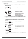
For the FX
1S, FX1N, FX1NC, FX2N and FX2NC PLCs
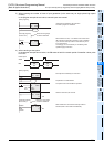
For the FX
0S, FX0, FX0N, FXU and FX2C PLCs
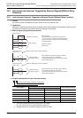
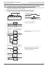
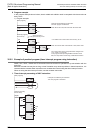
4) Using a pointer number two or more times
It is not possible to program an interrupt at the rising edge and an interrupt at the falling edge for an input
such as I001 or I000.
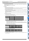
PLC Input number Input filter value when "0" is set
FX3U, FX3UC X000 to X005
5μs
*1
FX3G, FX3GC
X000, X001, X003, X004 10μs
X002, X005 50μs
FX3S
X000, X001 10μs
X002, X003, X004, X005 50μs
PLC Input number Pulse width
FX1S, FX1N, FX1NC
X000, X001 10μs
X002 to X005 50μs
FX
2N, FX2NC
X000, X001 20μs
X002 to X005 50μs
PLC Input number Pulse width
FX
0S, FX0, FX0N X000 to X003 100μs
FXU, FX2C X000 to X005 200μs