


11 Applied Instructions (Data Operation)
11.2 DECO / Decode
231
FXCPU Structured Programming Manual
[Basic & Applied Instruction]
11
Applied Instructions
(Data Operation)
12
Applied Instructions
(High Speed
Processing)
13
Applied Instructions
(Handy
Instruction)
14
Applied Instructions
(External FX I/O
Device)
15
Applied Instructions
(External Device
(optional device))
16
Applied Instructions
(External Device)
17
Applied Instructions
(Data Transfer 2)
18
Applied Instructions
(Floating Point)
19
Applied Instructions
(Data Operation 2)
20
Applied Instructions
(Positioning
Control)
Cautions
1) Instructions of pulse operation type are not provided in the FX0, FX0S or FX0N PLC.
To execute pulse operation, make the instruction execution condition pulse type.
2) While the command input is OFF, the instruction is not executed. The activated decode output is held in
the previous ON/OFF status.
3) When "n" is "0", the instruction executes no processing.
4) Some restrictions to applicable devices
S1:The FX
3G, FX3GC, FX3U and FX3UC PLCs only are applicable.
S2:The FX
3U and FX3UC PLCs only are applicable.
Program examples
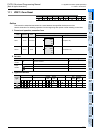
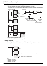
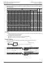
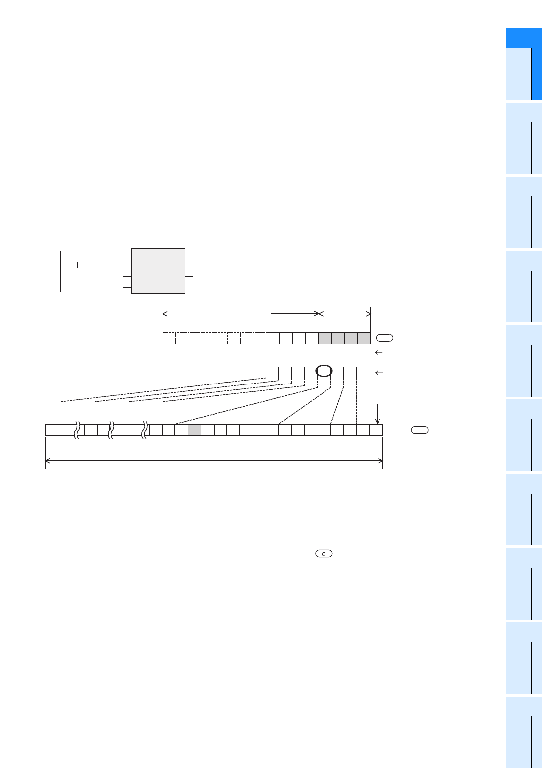
1. When setting bit devices to ON according to the value of a data register
The value of D0 (whose current value is "14" in this example) is decoded to M0 to M15.
• When the value of b0 to b3 of D0 is "14 (=0+2+4+8)", M14 (which is the 15th from M0) becomes "1" (turns
ON).
• When the value of D0 is "0", M0 becomes "1" (turns ON).
• When "n" is set to "K4", any one point among M0 to M15 turns ON according to the value of D0 (0 to 15).
• By changing "n" from K1 to K8, D0 can correspond to numeric values from 0 to 255.
However, because the device range of the device specified by is occupied for decoding accordingly,
such device range should not be used for another control.
Turns ON when D0 is K0.
(D0 b4 to b15)
0 0 0 0 1 1 1 0
b01234567
1
2
4
8
16
32
64
128
b15 ···
When the value of
b0 to b3 of D0 is "14"
0000000000000010
Up to 256 bits (The number of occupied bits varies depending on the specified "n" value.)
Up to
M31
Up to
M63
Up to
M127
Up to
M255
·········
K1K2K3K4K5K6K7K8
M255
M0M1M2M3M4M5M6M7M8M9
M10M11M12M13M14M15
When is M0
Ignored
4 bits
(D0 b0 to b3)
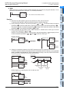
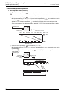
M8000
K4
D0
DECO
EN
s
n
ENO
d
M0
[Structured ladder/FBD]
[ ST ]
DECO(M8000, D0, K4, M0);
n=K4
2
n
s
d