


8 Applied Instructions (Move and Compare)
8.6 BMOV / Block Move
153
FXCPU Structured Programming Manual
[Basic & Applied Instruction]
1
Outline
2
Instruction List
3
Configuration of
Instruction
4
How to Read
Explanation of
Instructions
5
Basic Instruction
6
Step Ladder
Instructions
7
Applied Instructions
(Program Flow)
8
Applied Instructions
(Move and
Compare)
9
Applied Instructions
(Arithmetic and
Logical Operation)
10
Applied Instructions
(Rotation and
Shift Operation)
5) Handling of flash memory
<In FX
3U, FX3UC PLCs>
When changing the contents of file registers secured inside the flash memory, observe the following
condition:
- Set the protect switch to OFF in the optional memory.
- When writing data using a continuous operation type instruction in a program, data is written to the flash
memory in every operation cycle of the PLC.
To prevent this, as the flash memory has a limit to the number of times of writing operations, be sure to
use a pulse operation type instruction (BMOVP) so that the number of times of writing is reduced.
- It takes 66 to 132 ms to write data of one serial block (500 points) to the flash memory.
Execution of the program is paused during this period. Because the watchdog timer is not refreshed at
this time, it is necessary to take proper countermeasures such as inserting the WDT instruction into the
sequence program.
- Do not turn OFF the power while the contents of file registers are changed.
If the power is turned OFF during the change, the data stored in file registers may be filled with
unexpected values, or a parameter error may occur.
6) Write to the EEPROM
<In FX
3S, FX3G, FX3GC PLCs>
- It takes 80 ms to write data in one continuous block (500 points) to the EEPROM.
Note that execution of the program is paused during this period, but the watchdog timer is automatically
refreshed.
<In FX
1S, FX1N, FX1NC, FX2N and FX2NC PLCs>
- It takes 10 ms to write data in one point to the EEPROM.
Note that execution of the program is paused during this period, and the watchdog timer is automatically
refreshed.
<In FX
0N PLCs>
- Write to the EEPROM using peripheral equipment.
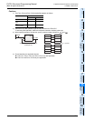
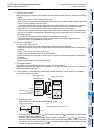
7) File register operation
File registers are secured inside the built-in memory or memory cassette.
Different from general data registers, file registers can be read and written directly only by peripheral
equipment or BMOV instruction.
8) If a file register is not specified as the destination in BMOV instruction, the file register is not accessed.
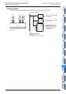
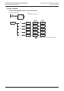
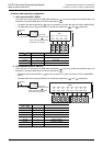
a) Outline of memory operation
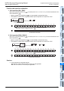
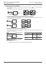
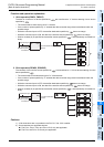
b) Program examples
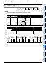
When X000 is set to ON, the data register area [B] is read.
A file register can be specified as . But if a same number with is specified, the same-number
register update mode is selected.
However, even if a file register having different number is specified for and respectively,
data cannot be transferred from the file register area to another file register area. In such a case, read
the contents of a file register specified as in the same-number register update mode to the data
register area [B] once, and then write the data.
Inside built-in RAM
or
optional cassette
D1000
Image
memory
D7999
D599
D 0
D200
D1499
D1100
Data register
[B]
Inside system RAM
Program
memory
Program/
comment
file
register
Data register
Data register
Read
500 points 14 blocks
maximum
(7000 points maximum)
[A]
X000
D1100 D200
BMOVP
EN
s
n
ENO
d
K400
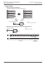
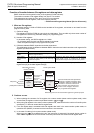
[Structured ladder/FBD]
[ ST ]
BMOVP(X000, D1100, K400, D200);