


14 Applied Instructions (External FX I/O Device)
14.5 SEGL / Seven Segment With Latch
369
FXCPU Structured Programming Manual
[Basic & Applied Instruction]
11
Applied Instructions
(Data Operation)
12
Applied Instructions
(High Speed
Processing)
13
Applied Instructions
(Handy
Instruction)
14
Applied Instructions
(External FX I/O
Device)
15
Applied Instructions
(External Device
(optional device))
16
Applied Instructions
(External Device)
17
Applied Instructions
(Data Transfer 2)
18
Applied Instructions
(Floating Point)
19
Applied Instructions
(Data Operation 2)
20
Applied Instructions
(Positioning
Control)
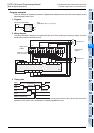
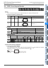
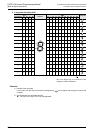
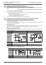
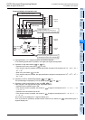
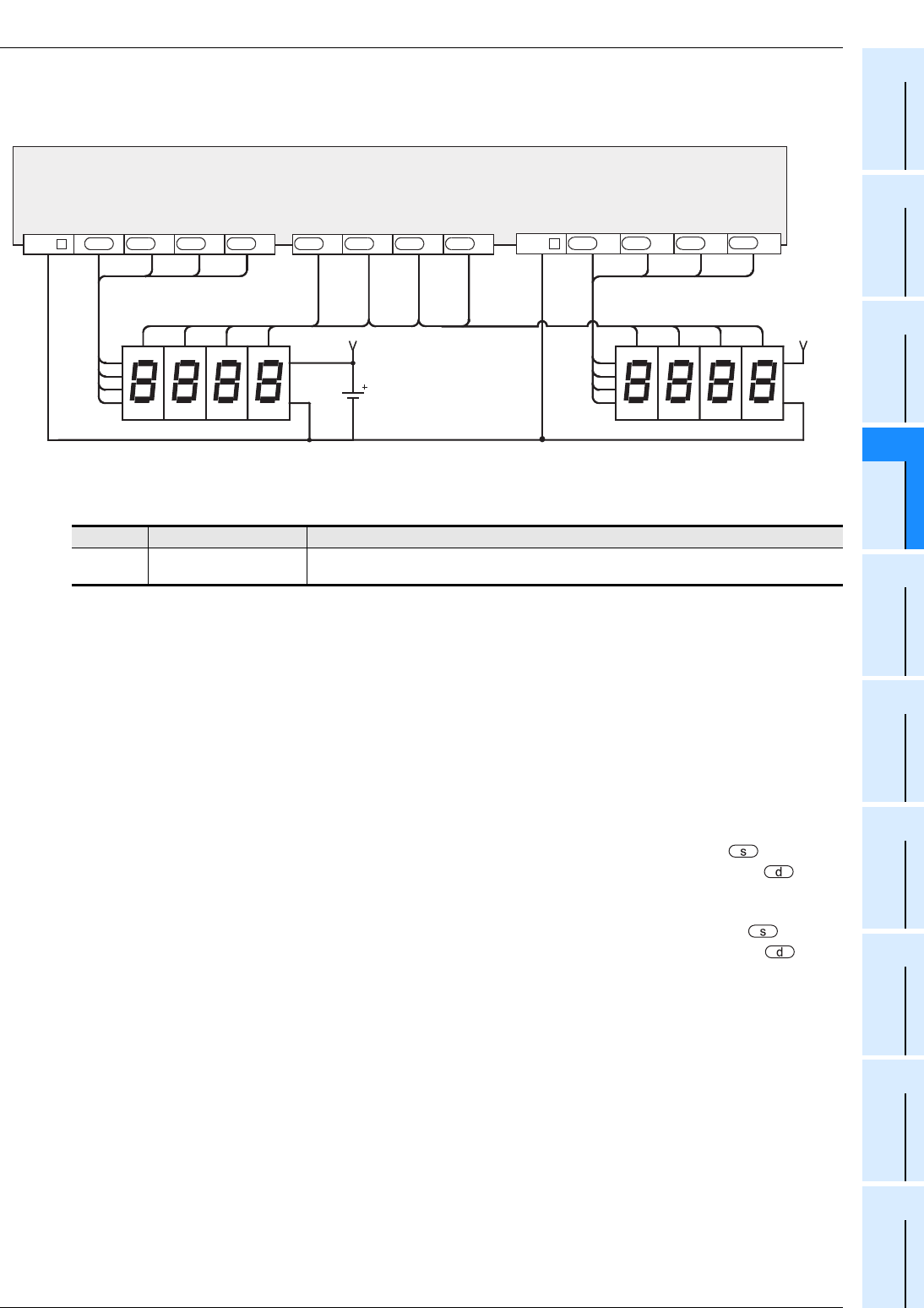
3) Connection example of 7-segment display unit
The following diagram show an example of FX
3U series basic unit (sync output).
As for the actual wiring, see the manual of the PLC.
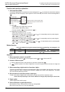
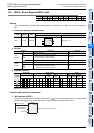
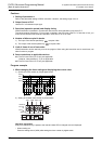
Related devices
→ As for the method of using the command execution complete flag, see paragraph 1.3.4.
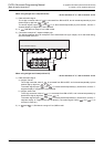
Cautions
1. Time for updating 7-segement 4-digit display
The time for updating the display of 4 digits (1 set or 2 sets) is required by 12 times of the scan time
(operation time).
2. Operation when command input is turned OFF
While the command input is ON, the operation is repeated, but once the command contact is turned OFF
during operation, the operation is interrupted, and when turned ON again, the operation is resumed from the
beginning.
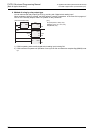
3. Number of bits occupied
When using 4 digits and 1 set : 1 point is occupied from the beginning device designated in .
8 points are occupied from the beginning device designated in . If the
number of digits is smaller, the remainder cannot be used in other
application.
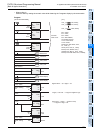
When using 4 digits and 2 sets: 2 points are occupied from the beginning device designated in .
12 points are occupied from the beginning device designated in . If the
number of digits is smaller, the remainder cannot be used in other
application.
4. Scan time (operation period) and display timing
SEGL command is executed in synchronism with the scan time (operation period) of the PLC.
For a series of display, the scan time of the PLC is required by 10 ms or more.
If less than 10 ms, you can operate in the scan time of 10 ms or more by using the constant scan mode.
5. Output format of PLC
Use the PLC of transistor output type.
6. Some restrictions to applicable devices.
S1: The FX3G, FX3GC, FX3U and FX3UC PLCs only are applicable.
S2: The FX
3U and FX3UC PLCs only are applicable.
Device Name Content
M8029
Command execution
complete
To be turned ON when output of 4 digits is over.
Second set
V+
1
2
4
8
10
3
10
2
10
1
10
0
PLC
(transistor output)
10
0
4
2
81
1
2
4
8
First set
V+
10
1
10
2
10
3
10
3
10
2
10
1
10
0
+3
d
+2
d
+1
dd
COM
+6
d
+5
d
+4
d
+7
d
4
2
8
1
COM +13
d
+12
d
+11
d
+10
d