94
FX3G/FX3U/FX3UC Series Programmable Controllers
Programming Manual - Basic & Applied Instruction Edition
4 Devices in Detail
4.5 Timer [T]
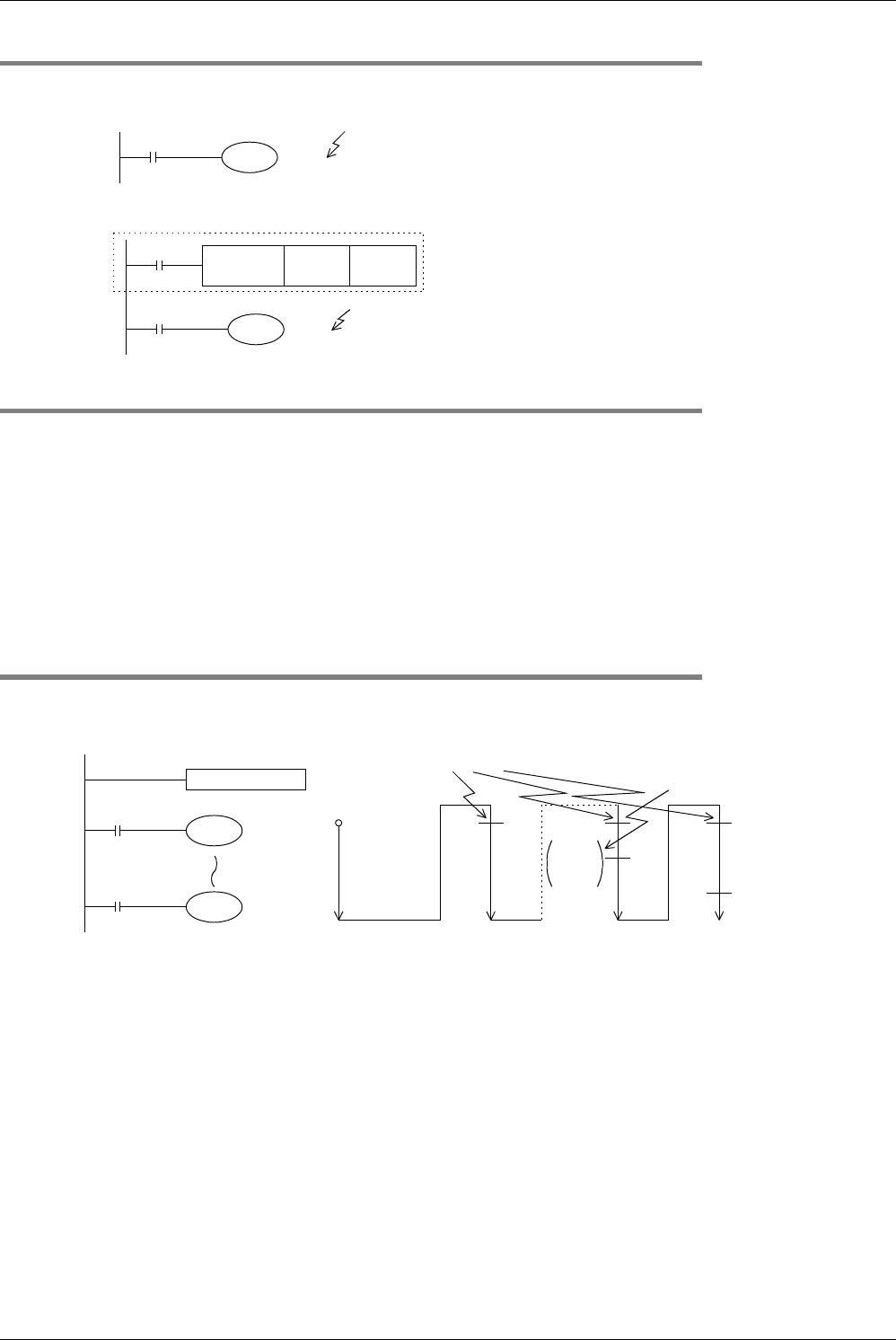
4.5.3 Set value specification method
1. Specifying a constant (K)
T10 is a 100 ms (0.1 sec) type timer.
When the constant "100" is specified, T10 works as a 10-
second timer (0.1 sec × 100 = 10 sec).
2. Indirectly specifying a data register
Turns on when T10 reaches the indirectly specified value of
the defined data register, previously set by a digital switch.
Note that the set value of a latched (battery backed) type
register is not held correctly sometimes when the battery
voltage becomes low.
4.5.4 Cautions on routines
1) Use timers T192 to T199 in subroutines and interrupt routines. These timers execute counting when a coil
instruction or END instruction is executed.
When such a timer reaches the set value, its output contact turns on when a coil instruction or END instruction is
executed.
Because general type timers execute counting only when a coil instruction is executed (Refer to "4.5.5 Details of
timer operation and timer accuracy" below.), they do not execute counting and do not operate normally if they are
used in subroutines or interrupt routines in which a coil instruction is executed only in a certain condition.
2) When a retentive timer for 1 ms pulses (T246 to T249) is used in a subroutine or interrupt routine, note that its
output contact turns on when the first coil instruction is executed after the retentive timer has reached the set
value.
4.5.5 Details of timer operation and timer accuracy
A timer (except interrupt execution type) starts counting when a coil is driven, and its output contact turns on when the
first coil instruction is executed after the timer has reached timeout.
As shown in the above operation diagram, the accuracy of operation of the timer contact after the coil is driven until the
contact turns on is shown in the following outline:
If the contact is programmed before the timer coil, "+2T
0" is obtained in the worst case.
When the timer set value is "0", the output contact turns on when a coil instruction is executed in the next cycle. An
interrupt execution type timer for 1 ms pulses counts clock pulses of 1 ms as an interrupt processing after a coil
instruction has been executed.
X003
T10
K100
Constant
(decimal integer)
10-second timer
D5 = K100
10-second
timer
X001
FNC 12
MOV
K100 D 5
X003
T10
D 5
X010
T 0
K12
T 0
Y010
Input processing
X010 = OFF
→
ON
Counting operation (If the operation cycle is long,
it automatically counts two or more clocks.)
Contact is not
activated at this point
T 0
Contact is
activated
2nd cycle "n"th cycle "n+1"th cycle
Y010
ON
Timer starts counting
1st cycle
1.2 sec
time-
out
α
: 0.001 sec (timer for 1 ms), 0.01 sec (timer for 10 ms) or 0.1 sec (timer for 100 ms)
T : Timer set value (sec)
T
0
: Operation cycle (sec)
T
+T
0
−α


