


111
FX3G/FX3U/FX3UC Series Programmable Controllers
Programming Manual - Basic & Applied Instruction Edition
4 Devices in Detail
4.7 High Speed Counter [C] (FX3U/FX3UC PLC)
1
Introduction
2
Overview
3
Instruction
List
4
Devices
in Detail
5
Specified the
Device &
Constant
6
Before
Programming
7
Basic
Instruction
8
FNC00-FNC09
Program Flow
9
FNC10-FNC19
Move & Compare
10
FNC20-FNC29
Arith. & Logic
Operation
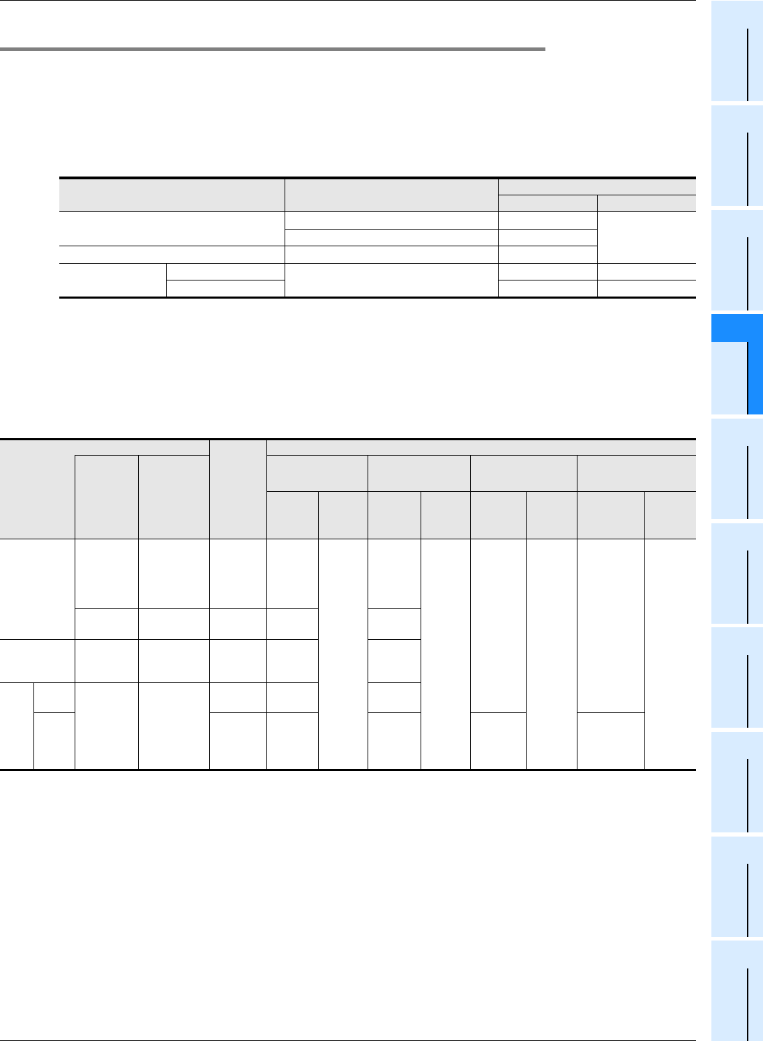
4.7.10 Response frequency of high speed counters
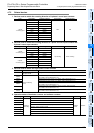
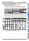
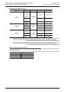
1. Response frequency of hardware counters
The table below shows the maximum response frequency of hardware counters.
When hardware counters are handled as software counters in some operating conditions, their maximum response
frequency becomes equivalent to that of software counters, and thus hardware counters are some times subject to
restrictions in total frequency.
→ For the conditions in which hardware counters are handled as software counters,
refer to the previous page.
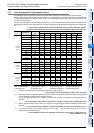
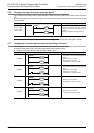
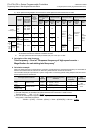
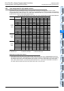
2. Response frequency and total frequency of software counters
The table below shows the maximum response frequency and total frequency of software counters.
When using the HSZ or HSCT instruction in a program, both the maximum response frequency and the total frequency
are limited for all software counters without regarding the operands of the instruction. When examining a system or
creating a program, consider the limitations, and use software counters within the allowable range of maximum
response frequency and total frequency.
→ For the conditions handled as software counters, refer to the previous page.
1) When special analog adapters and FX
3U/FX3UC Series special function blocks/units are not used
*1. When an index register is added to a counter number specified by a HSCS, HSCR, HSZ or HSCT instruction,
all hardware counters are switched to software counters.
*2. The high speed counters C244 (OP) and C245 (OP) can count up to 10 kHz.
Counter type Counter No.
Maximum response frequency
Main unit FX3U-4HSX-ADP
1-phase 1-counting input
C235, C236, C237, C238, C239, C240 100 kHz
200 kHzC244(OP), C245(OP) 10 kHz
1-phase 2-counting input C246, C248(OP) 100 kHz
2-phase 2-counting
input
1 edge count
C251, C253
50 kHz 100 kHz
4 edge count 50 kHz 100 kHz
Magnifica-
tion for
calculating
total
frequency
Response frequency and total frequency according to instructions used
Counter type
Software
counter
Following
software
counter with
HSCS, HSCR,
HSZ or HSCT
instruction
*1
When HSZ and HSCT
instructions are not
used
When only HSCT
instruction is used
When only HSZ
instruction is used
When both HSZ and HSCT
instructions are used
Maximum
response
frequency
(kHz)
Total
frequency
(kHz)
Maximum
response
frequency
(kHz)
Total
frequency
(kHz)
Maximum
response
frequency
(kHz)
Total
frequency
(kHz)
Maximum
response
frequency
(kHz)
Total
frequency
(kHz)
1-phase
1-counting
input
C241,
C242,
C243,
C244,
C245
C235, C236,
C237, C238,
C239, C240
×140
80
30
60
40 - (Num-
ber of
instruc-
tion)
*2
80−
1.5×(Num
ber of
instruc-
tion)
30-(Number
of instruc-
tion)
*2
60−
1.5×(Num
ber of
instruc-
tion)
−
C244(OP),
C245(OP)
×110 10
1-phase
2-counting
input
C247,
C248,
C249, C250
C246,
C248(OP)
×140 30
2-
phase
2-
count-
ing
input
1 edge
count
C252,
C253(OP),
C254,
C255
C251, C253
×140 30
4 edge
count
×410 7.5
(40-Num-
ber of
instruc-
tion) ÷ 4
(30-Number
of instruc-
tion) ÷ 4