


367
FX3G/FX3U/FX3UC Series Programmable Controllers
Programming Manual - Basic & Applied Instruction Edition
13 High Speed Processing – FNC 50 to FNC 59
13.6 FNC 55 – HSZ / High Speed Counter Zone Compare
11
FNC30-FNC39
Rotation and
Shift
12
FNC40-FNC49
Data Operation
13
FNC50-FNC59
High Speed
Processing
14
FMC60-FNC69
Handy
Instruction
15
FNC70-FNC79
External FX I/O
Device
16
FNC80-FNC89
External FX
Device
17
FNC100-FNC109
Data
Transfer 2
18
FNC110-FNC139
Floating Point
19
FNC140-FNC149
Data
Operation 2
20
FNC150-FNC159
Positioning
Control
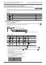
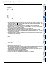
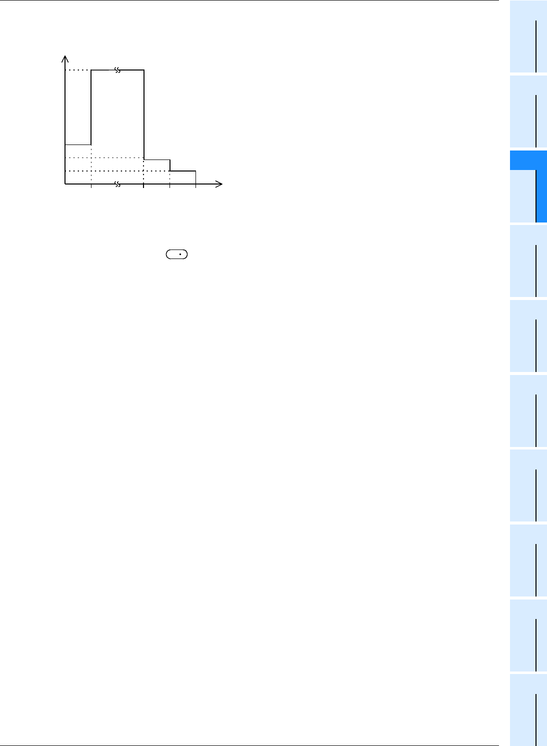
Output pulse characteristics
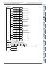
1) Write prescribed data in advance to data registers constructing the table as shown in this program example.
2) The output frequency of the PLSY instruction remains in the value (D303, D302) until the current value of a high
speed counter specified in becomes equivalent to (D301, D300). (D302 specifies low-order 16 bits. D303
specifies high-order 16 bits, but is always "0".)
3) The operation in the 2nd line is started after that, and then the operation in each line is executed in turn.
4) When the operation in the last line is completed, the complete flag M8133 turns ON. The program execution
returns to the 1st line, and the operation is repeated.
5) For stopping the operation in the last line, set the frequency in the last table to K0.
6) When the command input is set to OFF, the pulse output turns OFF and the table counter D8131 is reset.
7) After DHSZ instruction is first executed, creation of the table is completed at the END instruction. The DHSZ
instruction becomes valid after that.
8) Accordingly, the contact of PLS M10 is used so that the PLSY instruction is executed from the second scan after
the command input has been set to ON.
Data can be written to the table in a program as shown in this example or directly using keys in peripheral equipment.
1) M8132
This is the special auxiliary relay for declaring the frequency control mode
2) D8132
In the frequency control mode, the frequency set in the table is received by D8132 sequentially according to the
table counter count D8131.
3) D8134 (low-order) and D8135 (high-order)
In the frequency control mode, the comparison data in the table is received sequentially according to the table
counter count.
Cautions
1) DHSZ instruction can be used only once.
2) With regard to the DHSCS (FNC 53), DHSCR (FNC 54), DHSZ (FNC 55) and DHSCT (FNC280) instructions used
for other purposes, up to 32 instructions including the DHSZ instruction can be driven at one time.
3) Because the table is created when the END instruction is executed, it is necessary to delay execution of the PLSY
(FNC 57) instruction until creation of the table is completed.
4) Do not change the data table while the DHSZ instruction is driven.
5) In the frequency control mode, simultaneous output to Y000 to Y001 is not permitted.
→
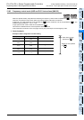
Current value of C251
Output pulse
frequency (Hz)
0
100
200
300
500
0 20 600 700 800
S