


783
FX3G/FX3U/FX3UC Series Programmable Controllers
Programming Manual - Basic & Applied Instruction Edition
35 SFC Program and Step Ladder
35.2 Step Ladder
31
FNC275-FNC279
Data
Transfer 3
32
FNC280-FNC289
High Speed
Processing 2
33
FNC290-FNC299
Extension File
Register
34
FNC300-FNC305
FX
3U
-CF-ADP
35
SFC•STL
Programming
36
Interrupt
Function
37
Special Device
38
Error Code
A
Version Up
Information
B
Execution Times
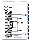
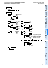
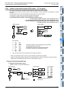
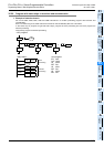
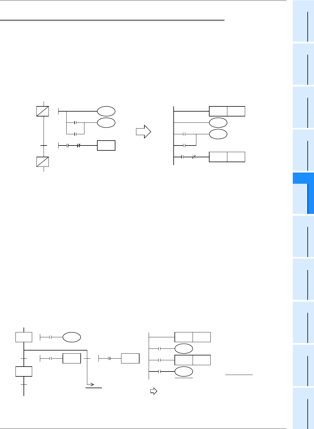
35.2.4 Creation of step ladder program (SFC program → STL program)
The figure on the left shows one state relay extracted as an example from an SFC program.
Each state relay has three functions, driving a load, specifying a transfer destination and specifying a transfer
condition.
The step ladder shown on the right expresses this SFC program as a relay sequence.
In this program, a load is driven, and then the ON status is transferred.
In a state relay without any load, the drive processing is not required.
For the program creation procedure, refer to the description on SFC programs.
→ For the program creation procedure, refer to Subsection 35.1.3.
→ For the handling and role of initial state relays, refer to Subsection 35.1.4.
→ For latched (battery backed) type state relays, refer to Subsection 35.1.5.
→ For RET instruction, refer to Subsection 35.1.6.
*1. SET and RST instructions for a state relay are two-step instructions.
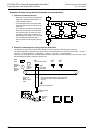
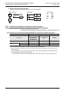
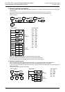
• When every state relay used in an SFC program is defined, programming is complete.
• Program a step ladder program starting from the initial state relay in the order of state relay ON status transfer.
Make sure to put the RET instruction at the end of a step ladder program.
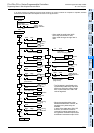
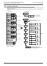
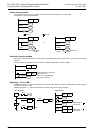
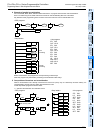
Program with jump/repeated flows
1. Program for the transfer source
Use OUT instruction in the jump/repeated part.
21
20
Y010
1
X011X000
TRAN
X010
Y010
STL S20
Y011
SET S21
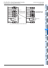
<Step ladder><SFC program>
SET
STL
Y011
X010
X011
X001
X000 X001
<List program>
0
1
2
3
4
5
6
7
STL
OUT
LD
OR
OUT
LD
ANI
SET
S20
Y010
X010
X011
Y011
X000
X001
S21
*1
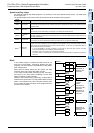
The above program can be expressed in the list format
(list program) shown on the left.
The segment from the STL instruction to the RET
instruction is handled as a step ladder program.
STL
LD
OUT
LD
SET
LD
OUT
41
40
Y001
1
X001
X003
X001
X002
TRAN
2
3
X003
TRAN
X002
Y001
STL S40
SET S41
S52
<Step ladder><SFC program>
52
<List program>
S40
X001
Y001
X002
S41
X003
S52
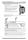
Jump/repeated part
Use OUT instruction in the jump/
repeated part.