


754
FX3G/FX3U/FX3UC Series Programmable Controllers
Programming Manual - Basic & Applied Instruction Edition
35 SFC Program and Step Ladder
35.1 SFC Program
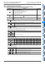
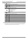
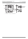
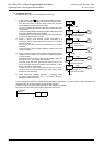
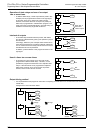
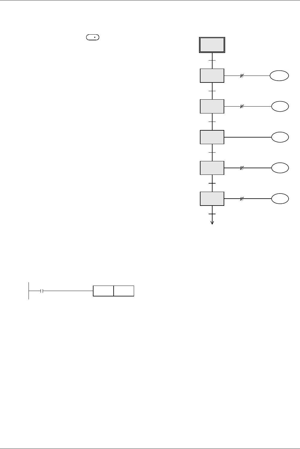
3. Assigning devices
Assign devices of a PLC in the created process drawing.
1) Assign a state relay to a rectangle indicating a process.
At this time, assign a state relay (S0 to S9) to the initial process.
After the first process, arbitrarily assign state relay numbers
(S20 to S899) except the initial state relays.
(There is no relationship between state relay numbers and order
of processes.)
There are latched (battery backed) type state relays whose ON/
OFF status is stored against power failure.
The state relays S10 to S19 are used for special purposes when
the IST (FNC 60) instruction is used.
2) Assign a device (input terminal number connected to a
pushbutton switch or limit switch, timer number, etc.) to each
transfer condition.
NO contact and NC contact are available for a transfer
condition.
If there are two or more transfer conditions, AND circuit or OR
circuit is available.
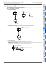
3) Assign a device (output terminal number connected to external
equipment, timer number, etc.) used for an operation performed
in each process.
Many devices such as timers, counters and auxiliary relays are
provided in a PLC, and can be used arbitrarily.
The timer T0 is used here. Because T0 works by the 0.1 sec
clock, the output contact turns ON five seconds after a coil is
driven when the set value is K50.
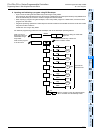
If there are two or more loads such as timers and counters
which are driven at the same time, two or more circuits can be
assigned to one state relay.
4) When performing repeated operations or skipping some
processes (jump operation), use “
” and specify the jump
destination state relay number.
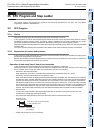
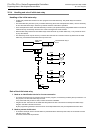
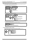
In this example, only the SFC program creating procedure is explained. In practical cases, a circuit for setting the
initial state relay to ON is required to execute the SFC program.
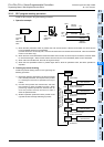
Create a circuit for setting the initial state relay to ON using the relay ladder.
At this time, use SET instruction to set the initial state relay to ON.
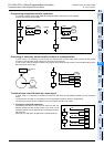
S0
S20
S21
S22
S23
S24
X001
X000
X002
T0
X002
X003
Y023
Y023
Y021
T0
K50
Y021
Y023
Y023
Y021
S0
Y021
Limit switch for minor
forward movement
Start switch
Limit switch for
backward movement
Timer
Limit switch for major
forward movement
Limit switch for
backward movement
Forward
Backward
Stop timer
Forward
Backward
S
M8002
SET S0
Initial pulse