247
FX3G/FX3U/FX3UC Series Programmable Controllers
Programming Manual - Basic & Applied Instruction Edition
9 Move and Compare – FNC 10 to FNC 19
9.3 FNC 12 – MOV / Move
1
Introduction
2
Overview
3
Instruction
List
4
Devices
in Detail
5
Specified the
Device &
Constant
6
Before
Programming
7
Basic
Instruction
8
FNC00-FNC09
Program Flow
9
FNC10-FNC19
Move & Compare
10
FNC20-FNC29
Arith. & Logic
Operation
Program examples
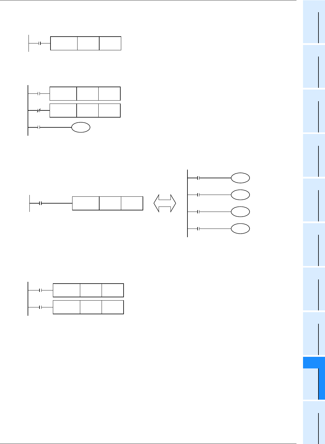
1. When reading the current value of a timer and counter
2. When indirectly specifying the set value of a timer or counter
As the set value of the timer T20, two values can be specified by turning ON or OFF the switch X002.
For specifying more than two set values, more than one switch is required.
3. When transferring a bit device
The program written by basic instructions shown on the right can be expressed using MOV instruction as shown
below.
4. When transferring 32-bit data
Make sure to use DMOV instruction for transferring the operation result of an applied instruction (such as MUL) whose
operation result is output in 32 bits, and for transferring a 32-bit numeric value or transferring the current value of a
high speed counter (C235 to C255) which is a 32-bit device.
X001
FNC 12
MOV
T 0 D 20
(Current value of T0)
→
(D20)
The operation is the same as a counter.
X002
FNC 12
MOV
K100 D 10
M 0
T 20
(K100)
→
(D 10)
When X002 is ON, D10 = K100 (10-second timer).
When X002 is OFF, D10 = K50 (5-second timer).
D 10
X002
FNC 12
MOV
K 50 D 10
(K50)
→
(D 10)
X000
X001
X002
X003
Y000
Y001
Y002
Y003
FNC 12
MOV
K1X000 K1Y000
M8000
RUN monitor
FNC 12
DMOV
C235
D20(D21)
FNC 12
DMOV
D0(D1)
D10(D11)
(D 1,D 0)
→
(D 11,D 10)
(Current value of C235)
→
(D21, D20)
Command
input
Command
input


