


207
FX3G/FX3U/FX3UC Series Programmable Controllers
Programming Manual - Basic & Applied Instruction Edition
7 Basic Instruction
7.12 PLS, PLF
1
Introduction
2
Overview
3
Instruction
List
4
Devices
in Detail
5
Specified the
Device &
Constant
6
Before
Programming
7
Basic
Instruction
8
FNC00-FNC09
Program Flow
9
FNC10-FNC19
Move & Compare
10
FNC20-FNC29
Arith. & Logic
Operation
7.12 PLS, PLF
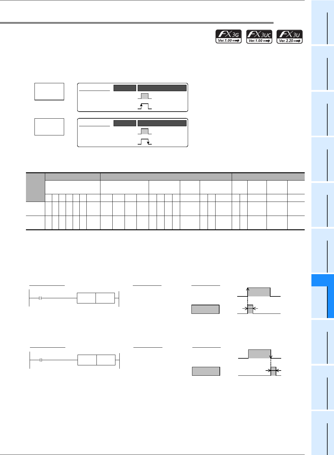
Outline
When PLS instruction is executed, an applicable device is activated during only one operation cycle after a drive input
turns ON.
When PLF instruction is executed, an applicable device is activated during only one operation cycle after a drive input
turns OFF.
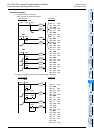
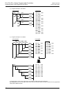
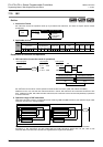
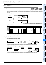
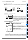
1. Instruction format
→ For the number of instruction steps, refer to Section 7.15.
2. Applicable devices
S1: Except special auxiliary relays (M)
S
2: This function is supported only in FX3U/FX3UC PLCs.
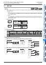
Explanation of function and operation
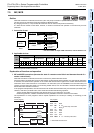
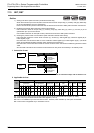
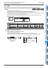
1. PLS instruction (rising edge pulse)
In the figure above, M0 is ON during only one operation cycle when X000 changes from OFF to ON.
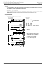
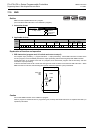
2. PLF instruction (falling/trailing edge pulse)
In the figure above, M1 is ON during only one operation cycle when X000 changes from ON to OFF.
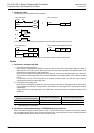
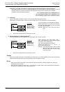
Instruc-
tion
Bit Devices Word Devices Others
System User Digit Specification System User
Special
Unit
Index
Con-
stant
Real
Number
Charac-
ter String
Pointer
XYMTCSD.b KnX KnY KnM KnS T C D R U\G VZModifyKH E ""P
PLS 3
S
1
S2
PLF 3
S
1
S2
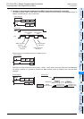
PLS
Pulse
Basic Instruction
PLS
−
Continuous
Operation
Pulse (Single)
Operation
Mnemonic Operation Condition
PLF
Pulse Falling
Basic Instruction
PLF
−
Continuous
Operation
Pulse (Single)
Operation
Mnemonic Operation Condition
ON
Circuit program List program Timing chart
X000
M0PLS
0000 LD X000
0001
PLS
M 0
X000
M 0
PLS
instruction
ON during
one operation
cycle
ON
Circuit program List program Timing chart
X000
M1PLF
0000 LD X000
0001
PLF
M 1
X000
M 1
PLF
instruction
ON during
one operation
cycle