


789
FX3G/FX3U/FX3UC Series Programmable Controllers
Programming Manual - Basic & Applied Instruction Edition
35 SFC Program and Step Ladder
35.2 Step Ladder
31
FNC275-FNC279
Data
Transfer 3
32
FNC280-FNC289
High Speed
Processing 2
33
FNC290-FNC299
Extension File
Register
34
FNC300-FNC305
FX
3U
-CF-ADP
35
SFC•STL
Programming
36
Interrupt
Function
37
Special Device
38
Error Code
A
Version Up
Information
B
Execution Times
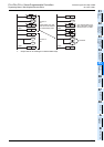
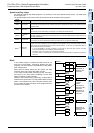
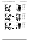
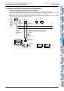
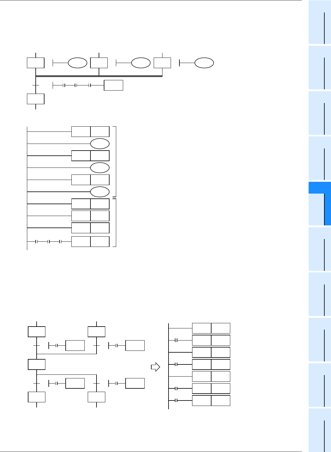
4. Example of parallel recombination
Do not use MPS, MRD, MPP, ANB and ORB instructions in a program with branches and recombination.
Even in a load driving circuit, MPS instructions cannot be used immediately after STL instructions.
Pay attention to the programming order so that a branch line does not cross a recombination line.
Before recombination, first program the drive processing of state relays.
After that, program only the transfer processing to recombination state relays.
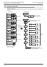
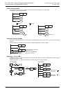
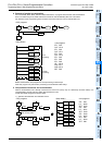
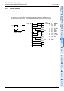
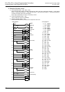
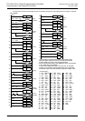
5. Composition of branches and recombination
When a recombination line is directly connected to a branch line (not by way of a state relay as shown below), it is
recommended to provide a dummy state relay between the lines.
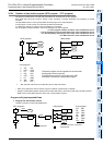
Create step ladder programs as shown below.
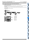
1) Selective recombination and selective branch
STL
OUT
STL
OUT
STL
OUT
STL
STL
STL
LD
AND
AND
SET
50
29
Y010
STL S29
STL S39
S29
Y010
S39
Y011
S49
Y012
S29
S39
S49
X010
X011
X012
S50
Y010
STL S49
39
Y011
49
Y012
Y011
Y012
STL S39
STL S49
STL S29
X010
SET S50
9
X010
TRAN
X011 X012
X011 X012
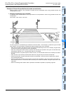
<Step ladder>
<List program>
<SFC program>
Drive
processing
Transfer
processing
STL
LD
SET
STL
LD
SET
STL
LD
SET
LD
SET
100
20
1
X000
X000
TRAN
2
X001
STL S20
SET S100
S20
X000
S100
S30
X001
S100
S100
X003
S50
X004
S60
30
3
50
60
X001
TRAN
X003
TRAN
4
X004
TRAN
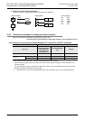
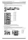
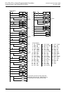
Dummy state
SET S100
STL S30
X003
SET S50
STL S100
X004
SET S60
<Step ladder>
<SFC program>
<List program>