302
FX3G/FX3U/FX3UC Series Programmable Controllers
Programming Manual - Basic & Applied Instruction Edition
11 Rotation and Shift Operation – FNC 30 to FNC 39
11.6 FNC 35 – SFTL / Bit Shift Left
Caution
Note that "n2" bits are shifted every time the command input turns ON from OFF in SFTLP instruction, but that "n2"
bits are shifted in each operation cycle in SFTL instruction.
Error
If the transfer source is equivalent to the shifted device in FX3U/FX3UC PLCs, an operation error occurs
(error code: K6710).
An operation error does not occur in FX
3G PLCs.
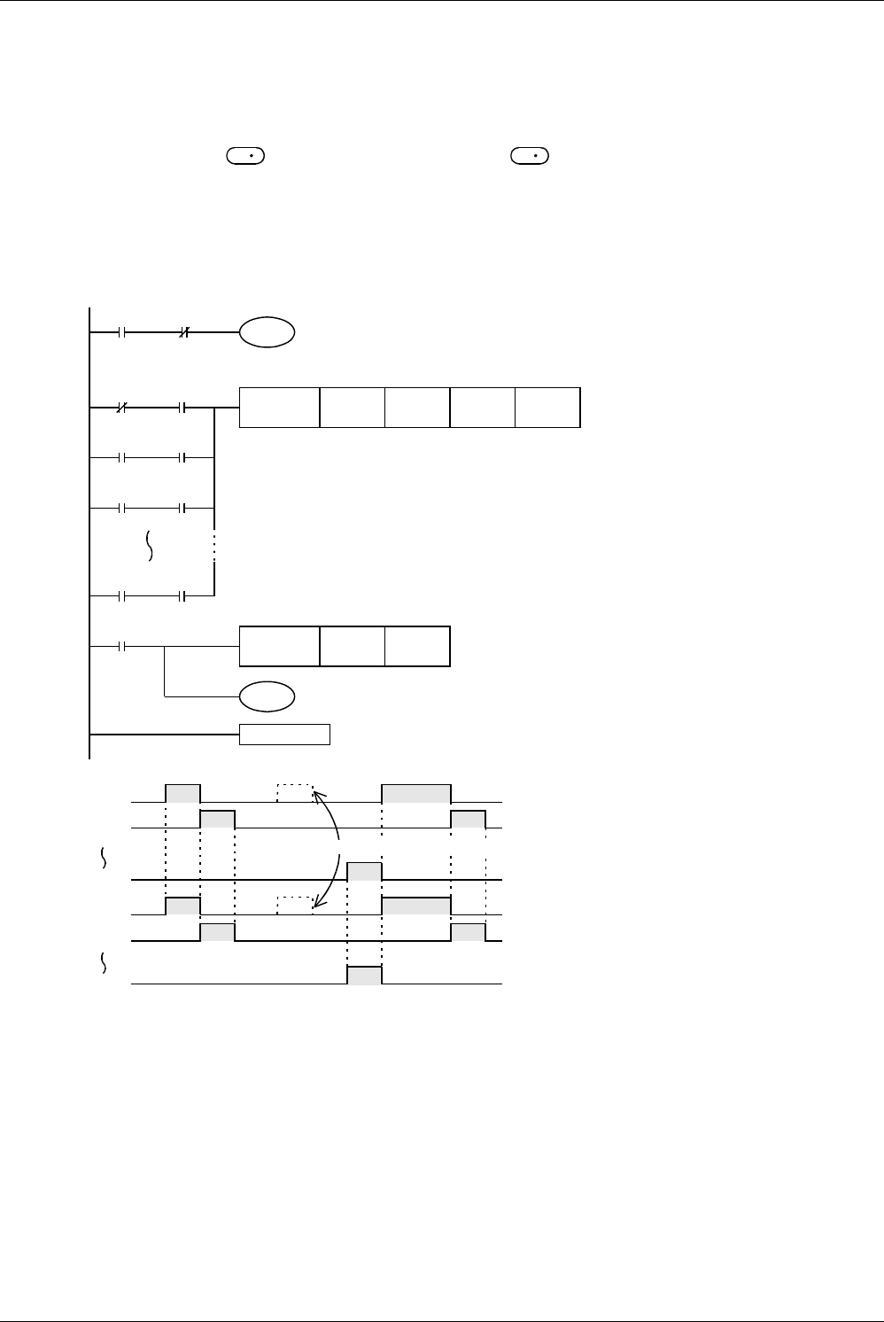
Program example (conditional stepping of 1-bit data)
By setting X000 to X007 to ON in turn, Y000 to Y007 are activated in turn.
If the order is wrong, activation is disabled.
S
D
X000
S 0
M8046
S 1
S 7
M8000
X000
M8046
X001
X002
X000
FNC 35
SFTL
M 0 S 0 K 8 K 1
M 0
Head data
Data
input
FNC 12
MOV
K2S 0 K2Y000
END
(S 7 to S 0)
→
(Y007 to Y000)
Bit 1 of M0 is regarded as the head input, and 8-bit shift register is
constructed by S0 to S7.
Even if X000 is set to ON, Y000 is not activated.
X000
X001
X007
Y001
Y007
Y000
*1
*1 By using a state relay (S), the state under operation can be monitored
by the dynamic monitoring function of the state relay.
M8047
STL monitor is valid.


