683
FX3G/FX3U/FX3UC Series Programmable Controllers
Programming Manual - Basic & Applied Instruction Edition
29 Data Table Operation – FNC250 to FNC269
29.7 FNC269 – SCL2 / Scaling 2 (Coordinate by X/Y Data)
21
FNC160-FNC169
Real Time Clock
Control
22
FNC170-FNC179
External Device
23
FNC180
Alternate
Instructions
24
FNC181-FNC189
Others
25
FNC190-FNC199
Block Data
Operation
26
FNC200-FNC209
Character String
Control
27
FNC210-FNC219
Data
Operation 3
28
FNC220-FNC249
Data
Comparison
29
FNC250-FNC269
Data Table
Operation
30
FNC270-FNC274
Ex-Device
Inverter Comms
Program example
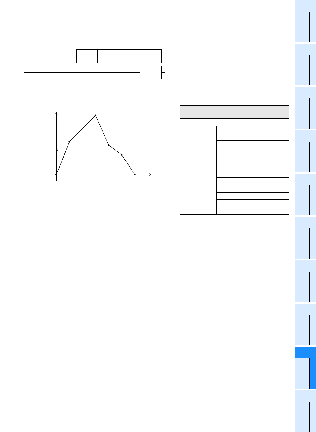
In the program example shown below, the value input to D0 is processed by scaling based on the conversion table for
scaling set in R0 and later, and output to D10.
Program
Operation
Conversion setting data table for scaling
Set item Device
Setting
contents
Number of coordinate points R0 K6
X coordinate
Point 1 R1 K0
Point 2 R2 K10
Point 3 R3 K30
Point 4 R4 K40
Point 5 R5 K50
Point 6 R6 K60
Y coordinate
Point 1 R7 K0
Point 2 R8 K50
Point 3 R9 K100
Point 4 R10 K45
Point 5 R11 K30
Point 6 R12 K0
M8000
R0 D10
FNC 269
SCL2
END
D0
Input value(D0)=7
Output value
(D10)=35
Point 1
(0,0)
X
Y
Point 2
(10,50)
Point 3
(30,100)
Point 4
(40,45)
Point 5
(50,30)
Point 6
(60,0)


