357
FX3G/FX3U/FX3UC Series Programmable Controllers
Programming Manual - Basic & Applied Instruction Edition
13 High Speed Processing – FNC 50 to FNC 59
13.6 FNC 55 – HSZ / High Speed Counter Zone Compare
11
FNC30-FNC39
Rotation and
Shift
12
FNC40-FNC49
Data Operation
13
FNC50-FNC59
High Speed
Processing
14
FMC60-FNC69
Handy
Instruction
15
FNC70-FNC79
External FX I/O
Device
16
FNC80-FNC89
External FX
Device
17
FNC100-FNC109
Data
Transfer 2
18
FNC110-FNC139
Floating Point
19
FNC140-FNC149
Data
Operation 2
20
FNC150-FNC159
Positioning
Control
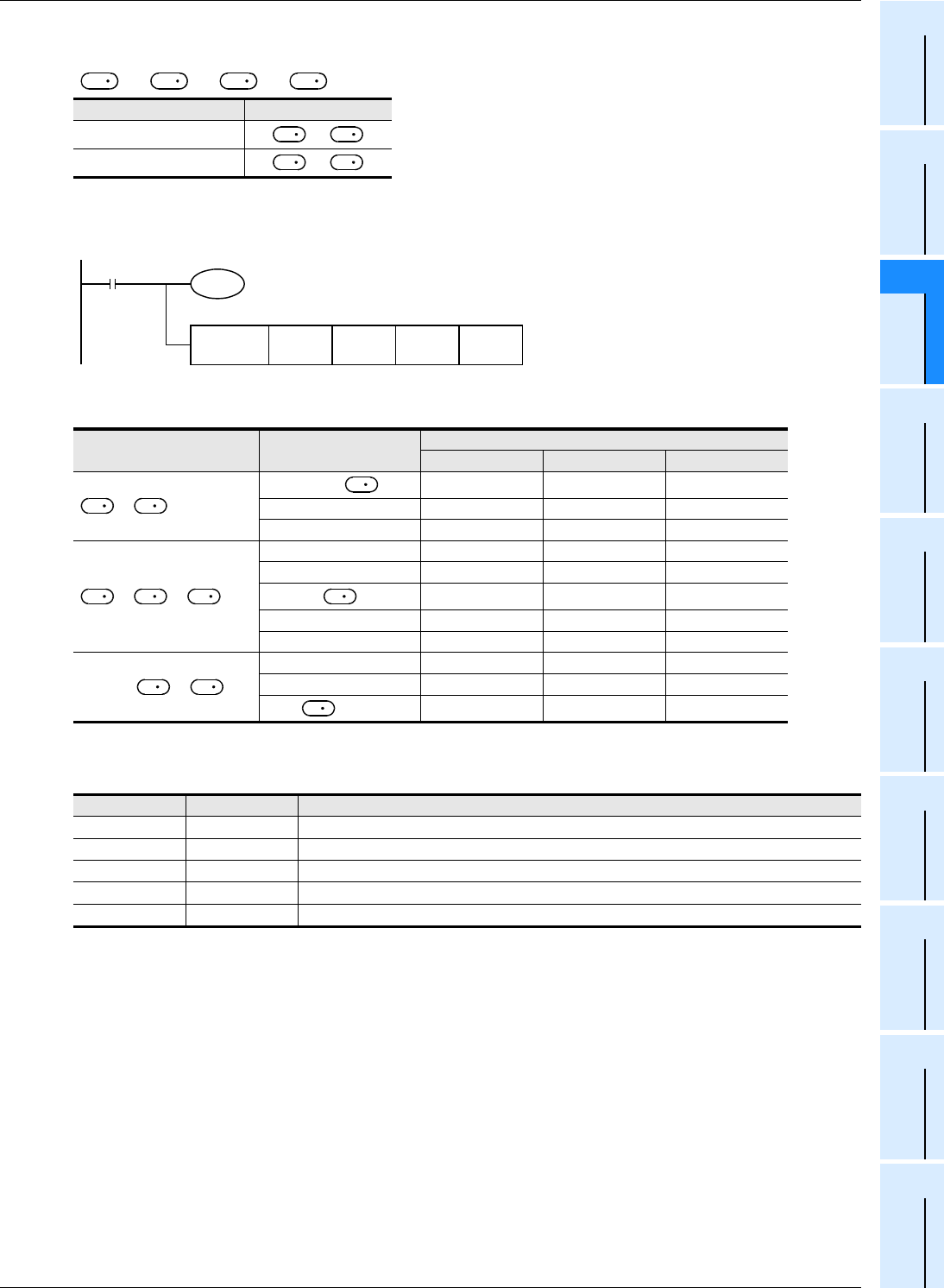
Comparison points
Make sure that the comparison value 1 and the comparison value 2 have the following relationship:
[+1, ] ≤ [+1, ]
Operation
When the current value of the high speed counter C251 changes (counts) as shown below, the comparison result is
output to one of the outputs Y000, Y001 or Y002.
Related instructions
The following instructions can be combined with high speed counters:
Comparison point Contents (32 bits)
Comparison value 1
+1,
Comparison value 2
+1,
Comparison pattern Current value of C251
Change of output contact (Y)
Y000 Y001 Y002
>
1000 >
ON OFF OFF
999 → 1000 ON → OFF OFF → ON OFF
999 ← 1000 OFF → ON ON → OFF OFF
≤ ≤
999 → 1000 ON → OFF OFF → ON OFF
999 ← 1000 OFF → ON ON → OFF OFF
1000 ≤ ≤ 2000
OFF ON OFF
2000 → 2001 OFF ON → OFF OFF → ON
2000 ← 2001 OFF OFF → ON ON → OFF
<
2000 → 2001 OFF ON → OFF OFF → ON
2000 ← 2001 OFF OFF → ON ON → OFF
> 2000
OFF OFF ON
Instruction FNC No. Instruction name
DHSCS FNC 53 High speed counter set
DHSCR FNC 54 High speed counter reset
DHSZ FNC 55 High speed counter zone compare
DHCMOV FNC189 High speed counter move
DHSCT FNC280 High speed counter compare with data table
S
1
S
1
S
2
S
2
S
1
S
1
S
2
S
2
C251
K2,147,483,647
FNC 55
DHSZ
K1000 K2000 Y000C251
→
Y000
K1000
≤
C251
≤
K2000
K1000
>
C251
C251
>
K2000
ON
M8000
RUN monitor
Comparison
value 2
Comparison
source
Output
destination
Comparison
value 1
→
Y001
→
Y002
S
1
S
S
S
1
S
S
2
S
S
S
2
S


