


255
FX3G/FX3U/FX3UC Series Programmable Controllers
Programming Manual - Basic & Applied Instruction Edition
9 Move and Compare – FNC 10 to FNC 19
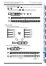
9.6 FNC 15 – BMOV / Block Move
1
Introduction
2
Overview
3
Instruction
List
4
Devices
in Detail
5
Specified the
Device &
Constant
6
Before
Programming
7
Basic
Instruction
8
FNC00-FNC09
Program Flow
9
FNC10-FNC19
Move & Compare
10
FNC20-FNC29
Arith. & Logic
Operation
2. Cautions on use
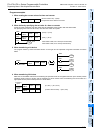
1) When updating the contents of a file register with a same number (same-number update mode), make sure that
the file register number is equivalent between and .
2) When using file registers in the same-number update mode, make sure that the number of transfer points
specified by "n" does not exceed the file register area.
3) If the file register area is exceeded while file registers are used in the same-number update mode, an operation
error (M8067) is caused and the instruction is not executed.
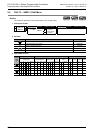
4) In the case of indexing (in the same-number update mode)
When and are indexing with index, the instruction is executed if the actual device number is within
the file register area and the number of transfer points does not exceed the file register area.
5) Handling of the memory cassette
When changing the contents of file registers secured inside the memory cassette, confirm the following
conditions:
- Set the protect switch of the memory cassette to OFF.
- It takes 66 to 132 ms to write data to one serial block (500 points) in the memory cassette (flash memory). It
takes 80 ms to write data to one serial block (500 points) in the memory cassette (EEPROM).
Execution of the program is paused during this period. Because the watchdog timer is not refreshed at this time,
it is necessary to take proper countermeasures such as insertion of WDT instruction in a user program.
6) Allowable number of times of writing to the memory
Data can be written to the memory cassette up to 10,000 times, and to the memory (EEPROM) built in FX
3G PLCs
up to 20,000 times.
When a continuous operation type instruction is used for data writing in a program, data is written to the memory
in every operation cycle of the PLC. To prevent this, make sure to use a pulse operation type instruction
(BMOVP).
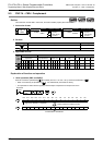
7) File register operation
File registers are secured inside the built-in memory or memory cassette.
Different from general data registers, file registers can be read and written only by peripheral equipment or BMOV
(FNC 15) instruction.
8) If a file register is not specified as the destination in BMOV (FNC 15) instruction, the file register is not accessed.
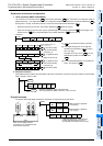
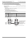
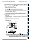
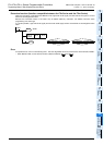
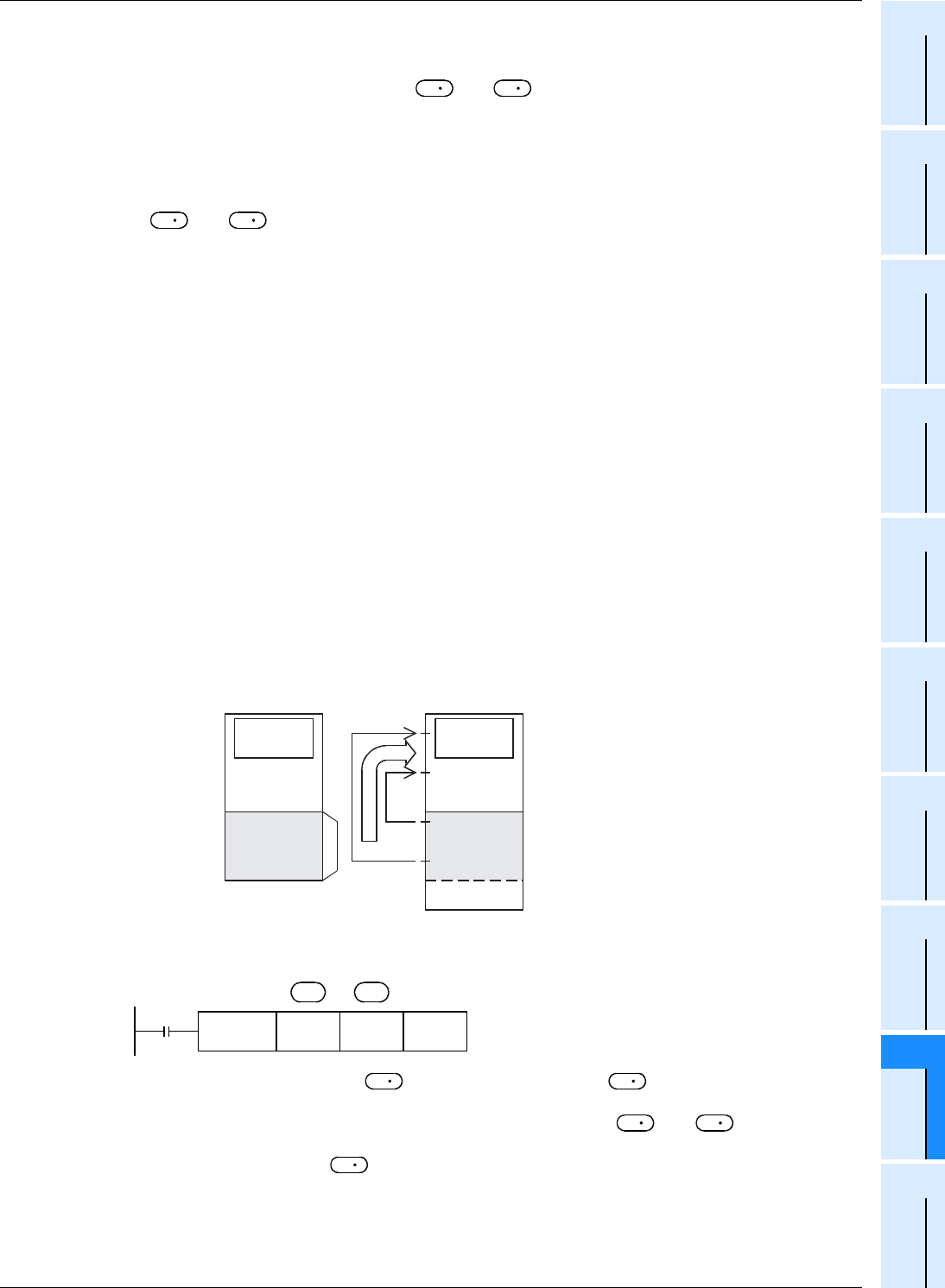
a) Outline of memory operation
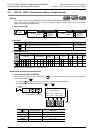
b) Program example
When X000 is set to ON, the data register area [B] is read.
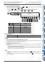
A file register can be specified as . But if a same number with is specified, the same-number
register update mode is selected.
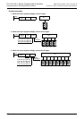
However, even if a file register having different number is specified for and respectively, data
cannot be transferred from the file register area to another file register area. In such a case, read the contents
of a file register specified as in the same-number register update mode to the data register area [B]
once, and then write the data.
→ For the same-number register update mode of file registers, refer to Subsection 4.8.2.
S
D
S
D
Data register
[B]
Inside system
RAM
Inside built-in memory
or memory cassette
Program
memory
Program/
comment
File register
[A]
D1000
Image
memory
Data register
Data register
D7999
D599
D 0
D200
Read
D1499
D1100
500 points ×
14 blocks
maximum
(7000 points
maximum)
X000
FNC 15
BMOVP
D1100 D200 K400
n
S
D
D
S
S
D
S