


193
FX3G/FX3U/FX3UC Series Programmable Controllers
Programming Manual - Basic & Applied Instruction Edition
7 Basic Instruction
7.5 LDP, LDF, ANDP, ANDF, ORP, ORF
1
Introduction
2
Overview
3
Instruction
List
4
Devices
in Detail
5
Specified the
Device &
Constant
6
Before
Programming
7
Basic
Instruction
8
FNC00-FNC09
Program Flow
9
FNC10-FNC19
Move & Compare
10
FNC20-FNC29
Arith. & Logic
Operation
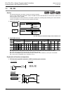
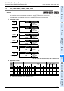
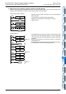
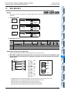
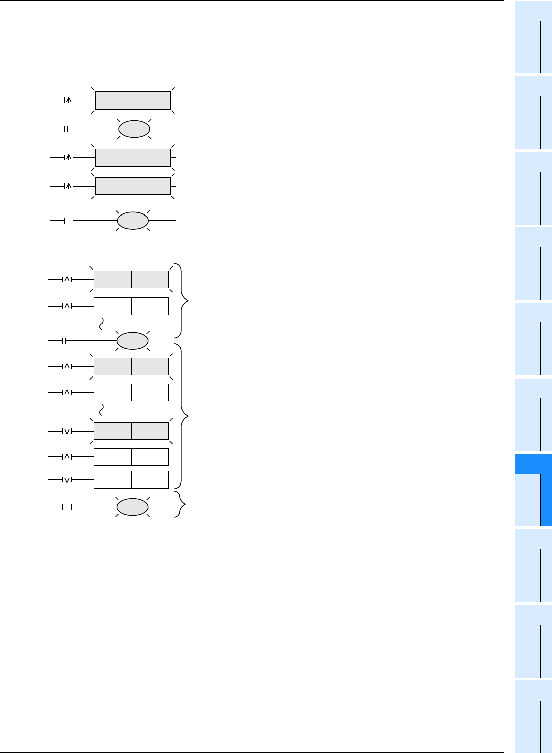
5. Differences in the operation caused by auxiliary relay (M) numbers
When an auxiliary relay (M) is specified as a device in LDP, LDF, ANDP, ANDF, ORP and ORF instructions, the
operation varies depending on the device number range as shown in the figure below.
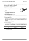
<M0 to M2799, M3072 to M7679>
After M0 is driven by X000, all contacts [1] to [4] corresponding to
M0 are activated.
•The contacts [1] to [3] detect the rising edge of M0.
•Because of LD instruction, the contact [4] is conductive
while M0 is ON.
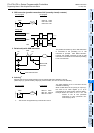
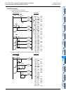
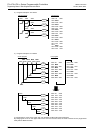
<M2800 to M3071>
From M2800 driven by X000, the program is divided into the upper
block (block A) and the lower block (block B). In each of the blocks
A and B, only the first contact which detects the rising or falling edge
is activated.
Because of LD instruction, the contact in the block C is conductive
while M2800 is ON.
By utilizing these characteristics, "transition of state by same signal"
in a step ladder circuit can be efficiently programmed.
M0
[1]
M0
M51
X000
M0
SET
[2]
M0
[4]
M0
M52SET
[3]
M50SET
M53
Block B
M2800
X000
M2800
M1SET
M0SET
M2800
M2800
M3SET
M2SET
M2800
M2800
M5SET
M4SET
M2800
M2800
M6SET
Block A
M7
M2800
Block C