


472
FX3G/FX3U/FX3UC Series Programmable Controllers
Programming Manual - Basic & Applied Instruction Edition
16 External FX Device – FNC 80 to FNC 89
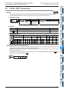
16.8 FNC 87 – RS2 / Serial Communication 2
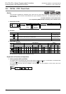
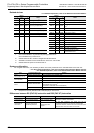
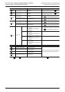
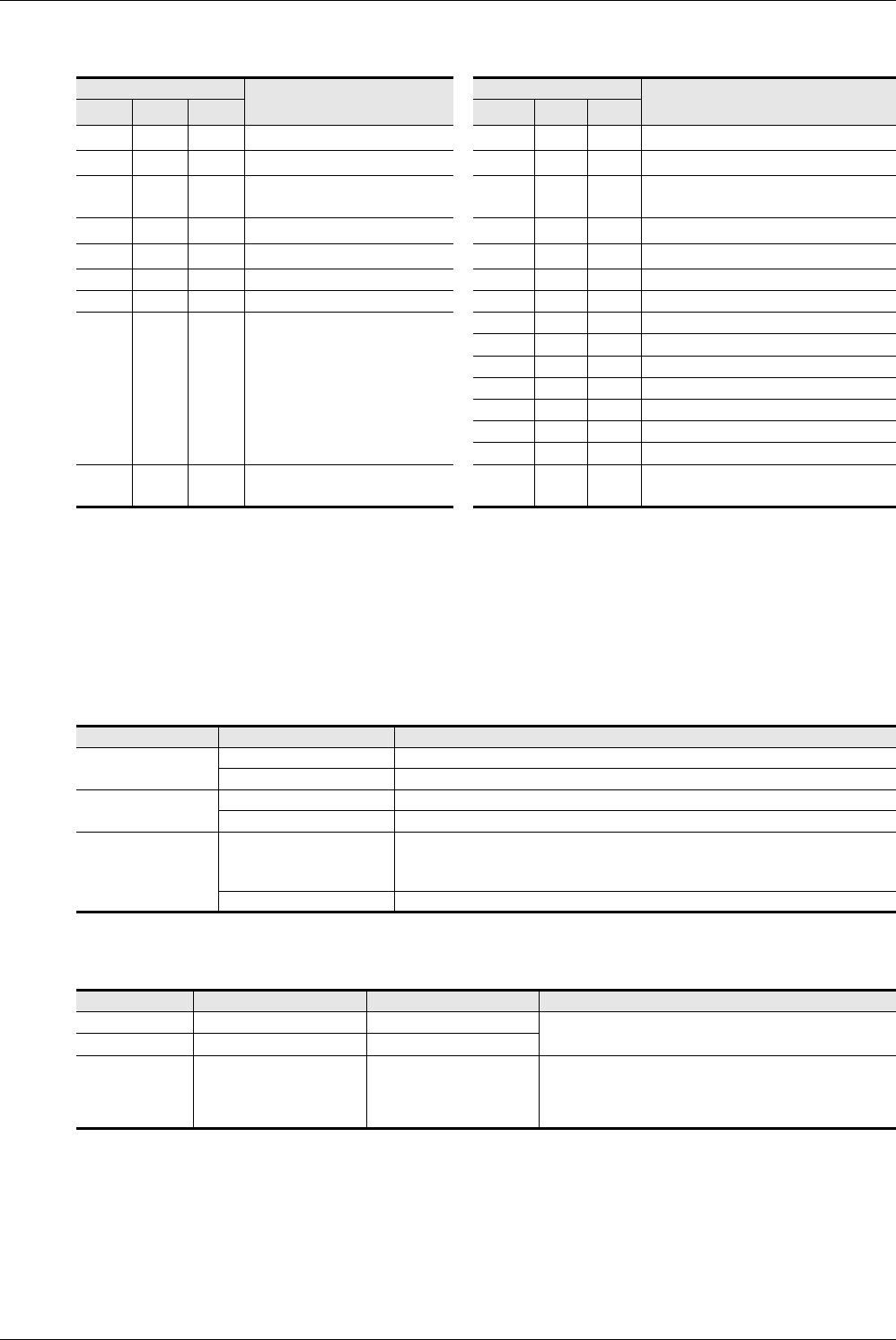
Related devices
→ For detailed explanation, refer to the Data Communication Edition.
*1. Ch2 is not available in 14-point and 24-point type FX
3G PLCs.
Ch0 is available only in FX
3G PLCs.
*2. Cleared when the PLC mode is changed from RUN to STOP.
*3. Available in all FX
3G PLCs and FX3U/FX3UC PLCs Ver. 2.30 or later.
*4. Cleared when the power is turned off and on.
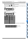
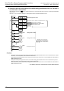
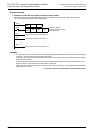
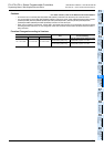
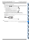
System configuration
For using this instruction, it is necessary to attach one of the products shown in the table below to the main unit.
→ For the system configuration, refer to the respective PLC Hardware Edition manual.
→ For detailed explanation, refer to the Data Communication Edition manual.
*1. Required to use ch0 (standard built-in RS-422 port) in FX
3G PLCs.
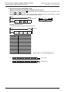
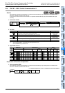
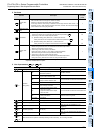
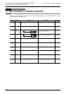
Differences between RS (FNC 80) instruction and RS2 (FNC 87) instruction
Device
Name
Device
Name
ch0
*1
ch1
ch2
*1
ch0
*1
ch1
ch2
*1
M8371 M8401 M8421
Sending wait flag
*2
M8370 D8400 D8420 Communication format setting
M8372 M8402 M8422
Sending request
*2
– −−
M8373 M8403 M8423
Receiving complete flag
*2
M8372 D8402 D8422
Remaining number of data to be
sent
*2
– M8404 M8424 Carrier detection flag M8373 D8403 D8423
Monitor for number of received data
*2
– M8405 M8425
Data Set Ready (DSR) Flag
*3
M8375 D8405 D8425 Communication parameter display
– – – – M8379 D8409 D8429 Time-out time setting
M8379 M8409 M8429 Time-out check flag M8380 D8410 D8430 Header 1, 2
– −− −
M8381 D8411 D8431 Header 3, 4
M8382 D8412 D8432 Terminator 1, 2
M8383 D8413 D8433 Terminator 3, 4
M8384 D8414 D8434 Receiving sum (received data)
M8385 D8415 D8435 Receiving sum (calculation result)
M8386 D8416 D8436 Sending sum
M8389 D8419 D8439 Operation mode display
M8062 M8063 M8438
Serial communication error
*4
M8062 D8063 D8438
Error code number of serial
communication error
*4
PLC Communication type Option
FX
3U,
FX
3UC-32MT-LT(-2)
RS-232C communication FX
3U-232-BD or FX3U-232ADP(-MB)
RS-485 communication FX
3U-485-BD or FX3U-485ADP(-MB)
FX
3UC(D,DSS)
RS-232C communication FX
3U-232ADP(-MB)
RS-485 communication FX
3U-485ADP(-MB)
FX
3G
RS-232C communication
FX
3G-232BD or FX3U-232ADP(-MB) (which requires FX3G-CNV-ADP)
RS-232C/RS-422 converter
*1
(FX-232AW, FX232AWC and FX-232AWC-H)
RS-485 communication FX
3G-485-BD or FX3U-485ADP(-MB) (which requires FX3G-CNV-ADP)
Item RS2 instruction RS instruction Remarks
Header size 1 to 4 characters (bytes) Up to 1 character (byte)
For the RS2 instruction, up to 4 characters (bytes) can be
specified as a header or terminator.
Terminator size 1 to 4 characters (bytes) Up to 1 character (byte)
Attachment of
check sum
The check sum can be
automatically attached.
The check sum should be
attached by a user
program.
For the RS2 instruction, the check sum can be
automatically attached to the sent and received data.
In this case, however, make sure to use a terminator in the
communication frame to be sent and received.