


81
FX3G/FX3U/FX3UC Series Programmable Controllers
Programming Manual - Basic & Applied Instruction Edition
4 Devices in Detail
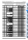
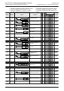
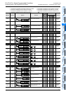
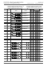
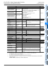
4.1 Device Number List
1
Introduction
2
Overview
3
Instruction
List
4
Devices
in Detail
5
Specified the
Device &
Constant
6
Before
Programming
7
Basic
Instruction
8
FNC00-FNC09
Program Flow
9
FNC10-FNC19
Move & Compare
10
FNC20-FNC29
Arith. & Logic
Operation
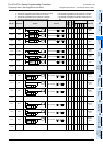
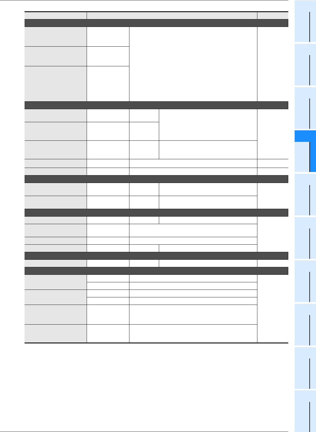
High speed counter
1-phase 1-counting input
Bi-directional (32 bits)
C235 to C245
8 points maximum can be used among C235 to C255 [latched
(battery backed) type].
The setting can be changed between the latched (battery
backed) type and the non-latch type using parameters.
−2,147,483,648 to 2,147,483,647 counts
Hardware counter
*3
1 phase: 100 kHz × 6 points, 10 kHz × 2 points
2 phases: 50 kHz (1 edge count),
50 kHz (4 edge count)
Software counter
1 phase: 40 kHz
2 phases: 40 kHz (1 edge count),
10 kHz (4 edge count)
Section 4.7
1-phase 2-counting input
Bi-directional (32 bits)
C246 to C250
2-phase 2-counting input
Bi-directional (32 bits)
C251 to C255
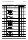
Data register (32 bits when used in pair form)
General type (16 bits)
[variable]
D0 to D199 200 points
The setting can be changed between the latched
(battery backed) type and the non-latched type
using parameters.
Section 4.9
latched (battery backed)
type (16 bits)
[variable]
D200 to D511 312 points
latched (battery backed)
type (16 bits)
[fixed] <file register>
D512 to D7999
<D1000 to
D7999>
7488 points
<7000
points>
Among the 7488 fixed latched (battery backed)
type data registers, D1000 and later can be set as
file registers in units of 500 points.
Special type (16 bits)
*2
D8000 to D8511 512 points Chapter 37
Index type (16 bits) V0 to V7, Z0 to Z7 16 points Section 4.11
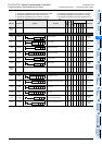
Extension register/Extension file register
Extension register
(16 bits)
R0 to R32767 32768 points latched (battery backed)
Section 4.10
Extension file register
(16 bits)
ER0 to ER32767
32768 points
Available only while a memory cassette is
mounted
Pointer
For jump and branch call P0 to P4095 4096 points For CJ and CALL instructions
Section 4.12
Input interrupt
Input delay interrupt
I0 to I5 6 points
Timer interrupt I6 to I8 3 points
Counter interrupt I010 to I060 6 points For HSCS instruction
Nesting
For master control N0 to N7 8 points For MC instruction
Constant
Decimal (K)
16 bits −32768 to +32767
Chapter 5
32 bits −2,147,483,648 to +2,147,483,647
Hexadecimal (H)
16 bits 0 to FFFF
32 bits 0 to FFFFFFFF
Real number (E) 32 bits
−1.0 × 2
128
to −1.0 × 2
−126
, 0, 1.0 × 2
−126
to 1.0 × 2
128
Both the decimal point expression and the exponent expression
are available.
Character string (" ") Character string
Specify characters by quotation marks.
In a constant of an instruction, up to 32 half-width characters are
available.
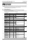
*1. Available device numbers vary depending on the PLC. For details, refer to Section 4.2.
*2. For supported functions, refer to Chapter 37.
For handling of the latched (battery backed) area, refer to Section 2.6.
*3. When the FX
3U-4HSX-ADP is connected to an FX3U PLC, the maximum input frequency is set as follows:
1 phase: 200 kHz
2 phases: 100 kHz (1 edge count). 100 kHz (4 edge count)
Device name Description Reference